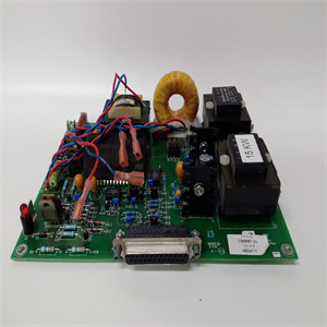
PM802F/PM803F/FI810F/SA801F工控模块系统备件
d不同于图1所示,取决于特定的模型。有关实际额定值和规格,请参阅产品铭牌或目录序列号表示开关的版本。系列字母的更改不会对兼容性产生任何影响。安装4 3安装3.1尺寸3.1.1 1/2英寸。NPT和3/4 NPT工艺连接[mm(in.)]图3.1:NPT尺寸22.7(0.89)68.5(2.70)63.9(2.52)47.9(1.89)M12 1/2 in。NPT或3/4英寸。NPT 1/2英寸。NPT或3/4英寸。NPT 161(6.34)1/2英寸。NPT阀门40(1.57)Ö40(Ö1.57)51.5(2.03)36(1.42)63.9(2.52)47.9(1.89)安装5 3.1.2 G 1/2工艺连接[mm(in.)]图3.2:G 1/2尺寸3.1.3产品选择22.7(0.89)68.5(2.70)63.9 2英寸。NPT阀840E-TB2B3A1E4 G 1/2 2线19…253V AC 100°C 1/2 NPT阀接头840E-TB2A1E4 3/4 in。NPT 2线19…253V AC 100°C 1/2 NPT阀接头840E-TB2B1A1E4 1/2 in。NPT 2线19…253V AC 100°C 1/2 NPT阀接头840E-TB1B3A1D4 G 1/2 3线PNP 10…35V DC 100°C M12接头840E-NB1B2A1D4 3/4 in。NPT三线PNP 10…35V DC 100°C M12接头840E-TB1B1A1D4 1/2 in。NPT 3线PNP 10…35V DC 100°C M12连接器目录号说明安装6 3.2安装说明3.2.1处理图3.3:握住外壳,而不是传感器叉图3.4:不要弯曲、缩短或拉长。Ra<3.2µm安装7 3.2.2安装示例图3.5:A=开关点,B=开关滞后A B B A A ~13(0.5)~10.5(0.41)~3(0.12)~2(0.08)~30(1.2)mm(in.)安装8 3.2.3粘度和堆积图3.6:考虑粘度和堆积。B D A C A B C D=0…10000 mm²/s=0…2000 mm²/s最小DN 50(2.0)[mm(in.)](0…15.50 in²/s)(0…3.10 in²/s!OFF ON OFF ON=0…10000 mm²/s=0…2000 mm²/s(0…15.50 in²/s)(0…3.10 in²/s)布线10 4布线4.1带M12连接器的DC-PNP版本图4.1:DC-PNP布线4.1.1匹配电缆[mm(in.)]2 m(6.5 ft)PVC电缆,带4针微型(M12x1)连接器和棘齿环氧涂层锌耦合螺母。目录号:889D-F4AC-2 2米(6.5英尺)PVC电缆,带4针微型(M12x1)直角连接器和棘轮环氧涂层锌耦合螺母。目录号:889D-R4AC-2注:其他电缆长度可用,某些模拟输出应用可能需要屏蔽电缆–有关更多信息,请参阅机上连接目录(出版物编号M115-CA001A-EN-P)。2 1 3 4 0.5 A L–L+R 1-棕色2-白色3-蓝色1 2 1 2 1 3 3 4 0.5 B L–L+R 1-棕色3-蓝色4-黑色1 4 1 4工作模式MAX(NC触点)工作模式MIN(NO触点)R=外部负载I=250 mA最大U=10…35 V DC 14(0.56)47(1.85)889D-F4AC-2 14(0.55)31.8(1.25)889D-R4AC-2接线11 4.1.2 DC-PNP操作图4.2:DC-PNP操作绿灯亮:传感器连接到电源并工作黄灯亮起:传感器浸入液体中红灯亮起:负载电路过载或短路-纠正短路-将最大负载电流降至250 mA以下绿灯熄灭:错误:无电源-检查插头、电缆和电源红灯闪烁:传感器内部错误
iffer from those shown in Figure 1, depending on particular model. Refer to product nameplate or catalog for actual ratings and specifications. • The series number indicates the version of the switch. A change in the series letter does not have any effect on the compatibility. Installation 4 3 Installation 3. 1 Dimensions 3.1.1 1/2 in. NPT and 3/4 NPT Process Connection [mm (in.)] Figure 3.1: NPT Dimensions 22.7 (0.89) 68.5 (2.70) 63.9 (2.52) 47.9 (1.89) M12 1/2 in. NPT OR 3/4 in. NPT 1/2 in. NPT OR 3/4 in. NPT 161 (6.34) 1/2 in. NPT VALVE 40 (1.57) Ø40 (Ø1.57) 51.5 (2.03) 36 (1.42) 63.9 (2.52) 47.9 (1.89) Installation 5 3.1.2 G 1/2 Process Connection [mm (in.)] Figure 3.2: G 1/2 Dimensions 3.1.3 Product Selection 22.7 (0.89) 68.5 (2.70) 63.9 (2.52) 38 (1.50) 16 (0.63) M12 G 1/2 63.9 (2.52) 38 (1.50) 16 (0.63) 161 (6.34) G 1/2 40 (1.57) Ø40 (Ø1.57) 51.5 (2.03) 36 (1.42) 1/2 in. NPT VALVE 840E-TB2B3A1E4 G 1/2 2-WIRE 19…253V AC 100 °C 1/2 NPT Valve Connector 840E-TB2B2A1E4 3/4 in. NPT 2-WIRE 19…253V AC 100 °C 1/2 NPT Valve Connector 840E-TB2B1A1E4 1/2 in. NPT 2-WIRE 19…253V AC 100 °C 1/2 NPT Valve Connector 840E-TB1B3A1D4 G 1/2 3-WIRE PNP 10…35V DC 100 °C M12 Connector 840E-TB1B2A1D4 3/4 in. NPT 3-WIRE PNP 10…35V DC 100 °C M12 Connector 840E-TB1B1A1D4 1/2 in. NPT 3-WIRE PNP 10…35V DC 100 °C M12 Connector Catalog Number Description Installation 6 3. 2 Installation Instructions 3.2.1 Handling Figure 3.3: Hold by the housing, not by the sensor fork Figure 3.4: Do not bend, shorten or lengthen. Ra < 3.2 µm Installation 7 3.2.2 Mounting Examples Figure 3.5: A = Switchpoint, B = Switching Hysteresis A B B A A ~13 (0.5) ~10.5 (0.41) ~3 (0.12) ~2 (0.08) ~30 (1.2) mm (in.) Installation 8 3.2.3 Viscosity and Build-up Figure 3.6: Take into account viscosity and build-up. B D A C A B C D = 0...10000 mm²/s = 0... 2000 mm²/s minimum DN 50 (2.0) [mm (in.)] ( 0...15.50 in²/s) ( 0...3.10 in²/s) Installation 9 3.2.4 Sensor Fork Alignment Figure 3.7: Align Sensor Fork (note mark) ! OFF ON OFF ON = 0...10000 mm²/s = 0... 2000 mm²/s ( 0...15.50 in²/s) ( 0...3.10 in²/s) Wiring 10 4 Wiring 4. 1 DC-PNP Version with M12 Connector Figure 4.1: DC-PNP Wiring 4.1.1 Mating Cables [mm (in.)] 2 m (6.5 ft) PVC Cable with 4-pin micro (M12x1) connector and ratcheted epoxy-coated zinc coupling nut. Catalog number: 889D-F4AC-2 2 m (6.5 ft) PVC Cable with 4-pin micro (M12x1) right-angle connector and ratcheted epoxy-coated zinc coupling nut. Catalog number: 889D-R4AC-2 Note: Other cable lengths are available and shielded cables may be required for some analog output applications – refer to the On-Machine Connectivity catalog (publication #M115-CA001A-EN-P) for additional information. 2 1 3 4 0.5 A L– L+ R 1 - Brown 2 - White 3 - Blue 1 2 1 2 2 1 3 4 0.5 A L– L+ R 1 - Brown 3 - Blue 4 - Black 1 4 1 4 Operating Mode MAX (NC Contact) Operating Mode MIN (NO Contact) R = External Load I = 250 mA Maximum U = 10...35 V DC 14 (0.56) 47 (1.85) 889D-F4AC-2 14 (0.56) 31.8 (1.25) 889D-R4AC-2 Wiring 11 4.1.2 DC-PNP Operation Figure 4.2: DC-PNP Operation Green light ON: Sensor is connected to power supply and operational Yellow light ON: Sensor is immersed in liquid Red light ON: Overload or short-circuit in load circuit - Rectify the short circuit - Reduce maximum load current to below 250 mA Green light OFF: Error: No power supply - Check plug, cable and power supply Red light flashing: Internal sensor error o


