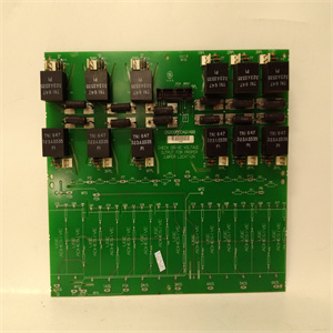
PM864 3BSE018151R1工控模块机器人备件
T该设备还符合USB电源管理和远程唤醒方案。在挂起期间,主机仅消耗最小功率。通过将所有功能集成在SOIC-28封装中,该芯片适合于电缆嵌入。用户只需将电缆连接到PC或集线器的USB端口,然后就可以连接到任何RS-232设备。引脚描述表1。引脚描述引脚编号名称类型描述1 TXD O数据输出到串行端口2 DTR_N O数据终端就绪,低激活3 RTS_N O请求发送,低激活4 VDD_232 P RS-232 VDD。RS-232输出信号(引脚1~引脚3)设计用于5V、3.3V或3V操作。VDD_232应连接到RS-232接口的相同功率电平。(RS-232输入信号始终允许5V~3V。)注意:本文档版本仅提供5V DC特性信息。有关更新,请参阅未来版本。5来自串行总线的RXD I数据输入6 RI_N I环指示灯,有效低7 GND P接地8 VDD P电源9 DSR_N I数据设置就绪,有效低10 DCD_N I数据载波检测,有效低11 CTS_N I清除发送,有效低12 SHTD_N O关闭RS232收发器13 EE_CLK I/O复位期间,此引脚输入用于模拟目的。正常操作期间,此引脚为串行ROM时钟14 EE_DATA I/O串行ROM数据信号15 DP I/O USB DPLUS信号16 DM I/O USB DMINUS信号17 USB收发器18 GND_3V3 P 3.3V电源19复位I系统复位20 VDD P电源21 GND P接地发布日期:2002年7月ds_pl2303_v14 PL-2303产品数据表-6-文件修订版1.3引脚号。名称类型描述22 TRI_STATE I三态复位后参考此引脚。高:挂起期间RS-232输出无效。低:挂起期间RS-232输出三态。23 LD_MD/SHTD I/O负载模式/SHTD此引脚在复位期间输入。用220K电阻器拉高,以指示重载USB设备(500mA)。用220K电阻器下拉,以指示轻负载USB设备100mA)。复位后,该引脚变为输出。它输出SHTD_N的倒数。24 VDD_PLL P PLL的5V电源25 GND_PLL P PLL 26 PLL_TEST I PLL测试模式控制27 OSC1 I晶体振荡器输入28 OSC2 O晶体振荡器输出类型:I–输入信号O–输出信号I/O–双向
his device is also compliant with USB power management and remote wakeup scheme. Only minimum power is consumed from the host during Suspend. By integrating all the function in a SOIC-28 package, this chip is suitable for cable embedding. Users just simply hook the cable into PC or hub’s USB port, and then they can connect to any RS-232 devices. Pin Description Table 1. Pins Description Pin No. Name Type Description 1 TXD O Data output to Serial port 2 DTR_N O Data Terminal Ready, active low 3 RTS_N O Request To Send, active low 4 VDD_232 P RS-232 VDD. The RS-232 output signals (Pin 1 ~ Pin 3) are designed for 5V, 3.3V or 3V operation. VDD_232 should be connected to the same power level of the RS-232 interface. (The RS-232 input signals are always 5V~3V tolerant.) Note: This document version only provides 5V DC characteristic information. Refer to future revisions for updates. 5 RXD I Data input from Serial Bus 6 RI_N I Ring Indicator, active low 7 GND P Ground 8 VDD P Power 9 DSR_N I Data Set Ready, active low 10 DCD_N I Data Carrier Detect, active low 11 CTS_N I Clear To Send, active low 12 SHTD_N O Shut Down RS232 Transceiver 13 EE_CLK I/O During Reset, this pin is input for simulation purpose. During normal operation, this pin is Serial ROM clock 14 EE_DATA I/O Serial ROM data signal 15 DP I/O USB DPLUS signal 16 DM I/O USB DMINUS signal 17 VDD_3V3 P 3.3V power for USB transceiver 18 GND_3V3 P 3.3V ground 19 RESET I System Reset 20 VDD P Power 21 GND P Ground Release Date: July, 2002 ds_pl2303_v14 PL-2303 Product Datasheet - 6 - Document Revision 1.3 Pin No. Name Type Description 22 TRI_STATE I Tri-State This pin is referred after reset. High: RS-232 output inactive during Suspend. Low: RS-232 output tri-state during Suspend. 23 LD_MD/ SHTD I/O Load Mode/SHTD This pin is input during reset. Pull high with a 220K resistor to indicate the heavy load USB device (500mA). Pull down with a 220K resistor to indicate the light load USB device 100mA). After reset, this pin becomes output. It output the inverse of SHTD_N. 24 VDD_PLL P 5V power for PLL 25 GND_PLL P Ground for PLL 26 PLL_TEST I PLL test mode control 27 OSC1 I Crystal oscillator input 28 OSC2 O Crystal oscillator output Type: I – Input signal O – Output signal I/O – Bi-directional


