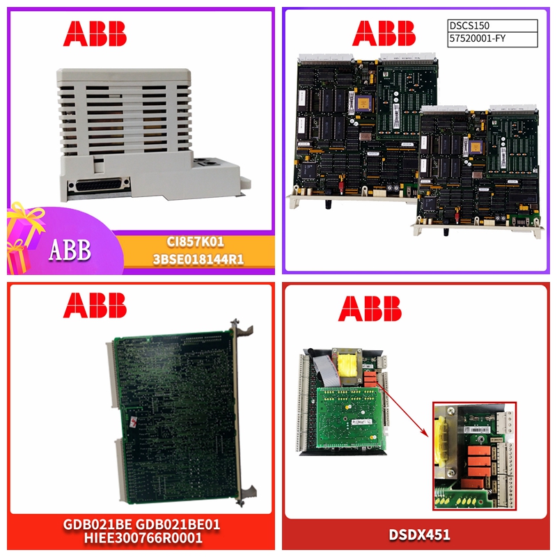
PPCC322BE HIEE300900R0001备件库存
所有w确保使用合适的棘轮型压接工具。压接导线和绝缘层。不要将多条电线连接到一个压接上。确保电源在第6.4节之前保持隔离和锁定。主交流电源必须在供电点通过最大500mA的高断裂容量(HRC)保险丝进行外部熔断。除非电源的中性侧参考接地,否则必须按照相同的规范进行熔断。28图26 440F-C4000P和440F-C4000 S(按照步骤1-12正确安装-见以下页面)N/O PB R IND MC MC 31 32 13 14 23 24 1 2 3 4–ve+ve N L A M 230 110 LED指示灯辅助保险丝500mA主保险丝500mA远程复位端子远程复位指示端子接触器监控端子辅助端子安全输出端子MAT连接端子1 3 2白色白色黑色黑色4 9 78 5 6 10 11机器启用绿色自动复位模式绿色手动复位模式绿色电源绿色模式设置手动自动电压设置110V 230V 24V日期勾选框29图26a 440F-C28013(按照步骤1-12正确安装-见以下页面)30 32 31 42 41 34 33 14 13 24 23 MC MC IND R PB NO NL+ve–ve 110V 230V自动复位手动复位24V N/C辅助端子N/O辅助端子安全输出端子N/C监控输出端子接触器监控端子远程复位端子MAT 1 MAT 2 MAT 3 MAT 4 MAT 5 MAT 6 MAT 7 MAT 8远程复位指示端子3 4 6 5 7 9 8 10 4 1 2 12 11模式设置手动自动电压设置110V 230V 24V日期复选框图。
Ensure that a suitable ratchet type crimping tool is used for all w. Crimp wires and insulation. Do not connect multiple wires to one crimp. Ensure that the power supply remains isolated and locked until Section 6.4. The main AC power supply must be externally fused through a high breaking capacity (HRC) fuse with a maximum of 500mA at the power supply point. Unless the neutral side of the power supply is referenced to ground, it must be fused according to the same specification. 28 Fig. 26 440F-C4000P and 440F-C4000 S (correctly installed according to steps 1-12 - see the following page) N/O PB R IND MC MC 31 32 13 23 24 1 2 3 4 – ve+ve N L A M 230 110 LED indicator light Auxiliary fuse 500mA Main fuse 500mA Remote reset terminal Remote reset indicator terminal Contactor monitoring terminal Auxiliary terminal Safety output terminal MAT connection terminal 1 3 2 White white black 4 9 78 5 6 10 11 Machine enabling green automatic reset mode Green power green mode Setting manual automatic voltage setting 110V 230V 24V Date check box 29 Figure 26a 440F-C28013 (correctly installed according to steps 1-12 - see the following page) 30 32 31 42 41 34 33 14 13 24 23 MC IND R PB NO NL+ve – ve 110V 230V automatic reset manual reset 24V N/C auxiliary terminal N/O auxiliary terminal safety output terminal N/C monitoring output terminal contactor monitoring terminal remote reset terminal MAT 1 MAT 2 MAT 3 MAT 4 MAT 5 MAT 6 MAT 7 MAT 8 remote reset indication terminal 3 4 6 7 9 8 10 4 1 2 11 mode setting manual automatic voltage setting 110V 230V 24V date check block diagram.


