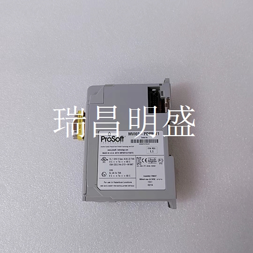
MVI69-PDPMV1 库存备件
安装说明原始说明PHOTOSWITCH系列5000模块化光电传感器产品目录号42MRU-5000、42MRU-5200、42MRP-5000、42MR R-5000、42MRI L-5000、42MRA 5000-FO、42MRF-5000-FO,42MRA-5000-FF,42MRA 5000-WA,42MRP-5000P、42MRF-35000-FF、42MRF 5000-WA、42MTB-5000、42MTB-0001、42MTB-3003、42MTB-4004、42MTB-502、42MTB5000QD5-1,42MTB-5004QD4-1变更汇总更新了目录号42MTB-5004的端子式电源底座接线图。说明5000系列模块化光电传感器由两个主要部件组成:光电头和电源底座。装有大部分电子器件的光电头只需拧一圈螺丝即可从电源底座上快速取出。如果应用程序发生变化,则切换到其他几个5000系列传感模式中的一种模式既快速又简单,无需重新布线或重新排列。PHOTOSWITCH®5000系列产品线中的六个产品系列可以解决许多困难的工业光电应用。功能•模块化封装提高了灵活性•多种传感模式•可选择明/暗操作•NPN和PNP输出•螺纹端子连接操作距离选择将传感器安装在相对清洁的环境中,以最大化操作距离。正常的工业环境从中度灰尘到肮脏。可能需要更大的操作裕度,这可以通过减小传感器的操作距离来获得。主题页更改摘要1描述1功能1操作距离选择1规格2端子式电源底座接线图3迷你快速断开接线图3典型响应曲线4端子式电源基座尺寸[mm(in.)]5电缆式电源底座尺寸5 QD型电源底座尺寸[mm。)]5透镜组件配件5直角镜适配器配件[mm(in.)]5通用安装组件6重型安装组件[mm(英寸)]
Installation Instructions Original Instructions PHOTOSWITCH Series 5000 Modular Photoelectric Sensors Catalog Numbers 42MRU-5000, 42MRU-5200, 42MRP-5000, 42MRR-5000, 42MRL-5000, 42MRA-5000-FO, 42MRF-5000-FO, 42MRA-5000-FF, 42MRA-5000-WA, 42MRP-5000P, 42MRF-5000-FF, 42MRF-5000-WA, 42MTB-5000, 42MTB-5001, 42MTB-5003, 42MTB-5004, 42MTB-5002, 42MTB5000QD5-1, 42MTB-5004QD4-1 Summary of Changes Updated terminal-style power base wiring diagram for Catalog Number 42MTB-5004. Description Series 5000 Modular Photoelectric Sensors consist of two major components: a photohead and a power base. The photohead that houses most of the electronics can be quickly removed from the power base with a turn of a screw. If an application changes, a switch to one of several other Series 5000 sensing modes is quick and easy—no rewiring or realignment. Six product families within the PHOTOSWITCH® Series 5000 product line can solve many difficult industrialphotoelectric applications. Features • Modular package for increased flexibility • Wide variety of sensing modes • Selectable light/dark operation • Both NPN and PNP outputs • Screw terminal connections Operating Distance Selection Install the sensor in a relatively clean environment to maximize operating distance. Normal industrial environments range from moderately dusty to dirty. Greater operating margin can be required, which can be obtained by reducing the operating distance of the sensor. Topic Page Summary of Changes 1 Description 1 Features 1 Operating Distance Selection 1 Specifications 2 Terminal Style Power Base Wiring Diagrams 3 Mini Quick-disconnect Wiring Diagrams 3 Typical Response Curves 4 Terminal-style Power Base Dimensions [mm (in.)] 5 Cable-style Power Base Dimensions 5 QD-style Power Base Dimensions [mm (in.)] 5 Lens Assembly Accessories 5 Right Angle Mirror Adapter Accessories [mm (in.)] 5 General-purpose Mounting Assembly 6 Heavy-duty Mounting Assembly [mm (in.)]


