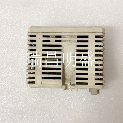
IMG_1627系统模块卡件
终端电阻器(135 W)OFF X X X 0终端电阻器(135W)ON X X X 1罗克韦尔自动化出版物45MLA-IN002C-EN-P-2020年8月11 45MLA控制器安装说明默认参数终端电阻器必须根据每个应用中的CAN架构进行设置,并且可以通过使用DIP开关阵列S2上的开关1来打开。可以使用DIP开关阵列S1(在主PCB上)设置通信速率和地址偏移。表27列出了先前讨论的附加参数的默认值(RJ485和CAN型号),可通过使用DIP开关阵列S1上的开关8进行重置,然后进行电源循环。近似尺寸尺寸单位为mm(in.)。附件45MLA系列的灯阵列(目录号45MLA-xxxxx0Pxx)作为透射光束对出售。表27-CAN模型的默认参数设置参数设置默认波束计数模式命令1C(十六进制),Par 46 0=第一波束电缆侧俯仰因子命令1C(六进制),Par 45 1覆盖波束命令1C(八进制),Par 43和44 0输出逻辑悬垂命令1C(九进制),Pars 24 0=激活“低”超高命令1C(五进制),Par 26 0=激活“低”悬垂载波区命令1C(十六进制),Par 23 1悬垂触发模式命令1C(六进制),Par 49 0=时间延迟模式延迟时间命令1C(八进制),和65 0 200(7.9)188(7.4)176(6.9)128(5.0)120(4.7)80(3.1)4.5(0.18)4x31(1.2)2x5.0(0.2)4x45(1.8)160(6.3)130(5.1)接收机阵列发射器阵列45MLA控制器出版物45MLA-IN002C-EN-P-2020年8月|取代出版物45MLA-IN002B-EN-P-2013年7月版权所有©2020 Rockwell Automation,Inc.保留所有权利。
Terminating resistor (135 W) OFF X X X 0 Terminating resistor (135 W) ON X X X 1 Rockwell Automation Publication 45MLA-IN002C-EN-P - August 2020 11 45MLA Controller Installation Instructions Default Parameters The termination resistor must be set according to the CAN architecture in each application and can be switched on through use of switch 1 on DIP switch array S2. The communication rate and address offset can be set with DIP switch array S1 (on the main PCB). Table 27 lists the default values for additional parameters that are previously discussed (for both RJ485 and CAN models), which can be reset by use of switch 8 on DIP switch array S1, followed by a power cycle. Approximate Dimensions Dimensions shown in mm (in.). Accessories Light arrays from the 45MLA family (Cat. No. 45MLA-xxxxx0Pxx) are sold as transmitted beam pairs. Table 27 - Default Parameter Settings for CAN model Parameter Setting Default Beam counting mode Command 1C (Hex), Par 46 0 = First beam cable side Pitch factor Command 1C (Hex), Par 45 1 Blanked Beams Command 1C (Hex), Par 43 and 44 0 Output logic overhang Command 1C (Hex), Par 24 0 = Active “Low” Over-height Command 1C (Hex), Par 25 1 Output logic over-height Command 1C (Hex), Par 26 0 = Active “Low” Overhang carrier zone Command 1C (Hex), Par 23 1 Overhang trigger mode Command 1C (Hex), Par 49 0 = time delay mode Delay times Command 1C (Hex), Par 63, 64, and 65 0 200 (7.9) 188 (7.4) 176 (6.9) 128 (5.0) 120 (4.7) 80 (3.1) 4.5 (0.18)4x 31 (1.2) 2x 5.0 (0.2) 4x 45 (1.8) 160 (6.3) 130 (5.1) Receiver Array Emitter Array 45MLA Controller Publication 45MLA-IN002C-EN-P - August 2020 | Supersedes Publication 45MLA-IN002B-EN-P-July 2013 Copyright © 2020 Rockwell Automation, Inc. All rights reserved.


