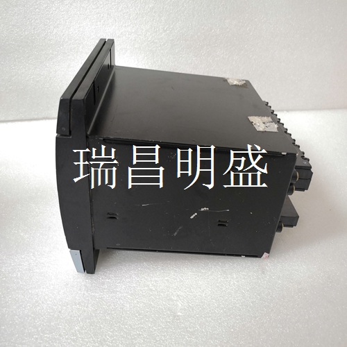
GE MIFIIPI55E10HI00 处理器模块
24 VDC 0 VDC表12-J2引脚列表引脚信号说明备注1 0V DC电源-2+24V DC电源-3接地-4未连接未连接-5入2触发并保持DIP开关S1(7)=0后悬传感器DIP开关S2(7)=1 6入1未使用DIP开关S3(7)=0前悬传感器DIP开关S1(8)=1 7出2灯阵列中断(1)(1)或高度过高(特殊功能)0V DC=中断的24V DC=未中断的8输出1悬垂0V DC=悬垂24V DC=无悬垂表13-J14引脚列表引脚信号0V DC+24V DC 1输出3区域Z1中断区域Z1未中断2输出4区域Z2中断区域Z2未中断3输出5区域Z3中断区域Z3未中断4输出6区域Z4中断区域Z4未中断表14-I/O板状态指示器状态指示器描述状态含义D10区域1关闭输出3=关闭(0V DC)绿色输出3=打开(24V DC)D11区域2关闭输出4=关闭(0 V DC)绿色出口4=打开(24 V DC)D12区域3关闭输出5=关断(0 V直流)绿色输出5=开启(24 V直流)D13区域4关闭输出6=关闭(V DC)蓝色输出6=打开(24VDC)D14示教关闭非激活闪烁示教进行中橙色最后一个示教步骤罗克韦尔自动化出版物45MLA-IN002C-EN-P-2020年8月7 45MLA控制器安装说明DIP开关设置S1 DIP开关阵列上的DIP开关1…6配置用于表15中所述的各种应用。如果未提供其他信息,这些DIP开关应保持在OFF位置。DIP开关7用于配置悬垂模式(更多信息请参见出版物10000071139),DIP开关8用于重置默认配置。一旦更改,DIP开关设置仅在电源循环后才能识别。表15详细说明了I/O板的DIP开关设置。有关所列功能的更多信息,请参阅编程指南。默认参数表16列出了前面讨论的每个参数的默认值,可以通过使用DIP开关阵列S1上的开关8进行重置,然后进行电源循环。示教过程示教功能允许您通过使用I/O扩展PCB上的按钮配置多个功能的参数。以下各节详细介绍了可教给传感器的参数以及与此程序相关的步骤。
24 VDC 0 VDC Table 12 - J2 Pin Listings Pin Signal Description Remarks 1 0V DC Power — 2 +24V DC Power — 3 Ground Ground — 4 Not connected Not connected — 5 In 2 Trigger and hold DIP switch S1 (7) = 0 Overhang back sensor DIP switch S1 (7) = 1 6 In 1 Not used DIP switch S1 (7) = 0 Overhang front sensor DIP switch S1 (7) = 1 7 Out 2 Light array interrupted (1) (1) Or over-height (special function) 0V DC = interrupted 24V DC = not interrupted 8 Out 1 Overhang 0V DC = overhang 24V DC = no overhang Table 13 - J14 Pin Listings Pin Signal 0V DC +24V DC 1 Out 3 Zone Z1 interrupted Zone Z1 not interrupted 2 Out 4 Zone Z2 interrupted Zone Z2 not interrupted 3 Out 5 Zone Z3 interrupted Zone Z3 not interrupted 4 Out 6 Zone Z4 interrupted Zone Z4 not interrupted Table 14 - I/O Board Status Indicators Status Indicator Description Status Meaning D10 Zone 1 Off Out 3 = OFF (0V DC) Green Out 3 = ON (24V DC) D11 Zone 2 Off Out 4 = OFF (0V DC) Green Out 4 = ON (24V DC) D12 Zone 3 Off Out 5 = OFF (0V DC) Green Out 5 = ON (24V DC) D13 Zone 4 Off Out 6 = OFF (0V DC) Green Out 6 = ON (24V DC) D14 Teach Off Teach inactive Flashing Teach in progress Orange Last teach step Rockwell Automation Publication 45MLA-IN002C-EN-P - August 2020 7 45MLA Controller Installation Instructions DIP Switch Settings DIP switches 1…6 on the S1 DIP switch array are configured for the various applications that are described in Table 15. If no information is otherwise provided, these DIP switches should remain in the OFF position. DIP switch 7 is used to configure the overhang mode (see Publication 10000071139 for further information) and DIP switch 8 is used to reset default configuration. Once changed, DIP switch settings are only recognized after a power cycle. Table 15 details DIP switch settings for the I/O board. See the Programming Guide for further information on the listed functions. Default Parameters Table 16 lists the default values for each of the parameters that are previously discussed, that can be reset by use of switch 8 on DIP switch array S1, followed by a power cycle. Teach Process The teach function allows you to configure the parameters for a number of functions by use of a push button on the I/O extension PCB. The following sections detail the parameters that can be taught to the sensor, and the steps associated with this procedure.


