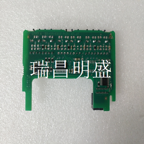
ABB UFD203A101 3BHE019361R0101 系统模块卡件
也可以仅连接到一个插头。CAN模块由内部供电。不使用CAN电源(接头J12和13,针脚7和8),而是串联连接。图9-CAN型号引脚状态指示器表24显示了CAN扩展PCB上状态指示器D8和D10的含义。DIP开关设置表25和表26描述了CAN型号的DIP开关的设置。扩展PCB上的DIP开关阵列S2(1…4)设置地址偏移,影响CAN标准模式和扩展CAN模式的所有基本地址。DIP开关设置更改仅在电源循环后生效。表24-CAN控制器状态指示灯状态指示灯描述颜色含义D8 CAN错误关闭无CAN错误红色CAN错误–无效消息D10 CAN通信关闭无通信绿色闪烁控制器通过CAN 1 2 3 4 5 6 7 8 CAN H CAN L C.GND C.SHIELD C.GND CAN V+1 2 3 4 6 7 8 CANH CAN L C GND C。GND CAN V+表25-DIP开关阵列S1设置功能阵列S1(1)(1)上的DIP开关编号(0:关,1:开,X:不相关 0终端电阻器(135 W)OFF X X X 0终端电阻器ON X X X 1罗克韦尔自动化出版物45MLA-IN002C-EN-P-2020年8月11 45MLA控制器安装说明默认参数终端电阻器必须根据每个应用中的CAN架构设置,并且可以通过使用DIP上的开关1打开可以使用DIP开关阵列S1(在主PCB上)设置通信速率和地址偏移。表27列出了先前讨论的附加参数的默认值(RJ485和CAN型号),可通过使用DIP开关阵列S1上的开关8进行重置,然后进行电源循环。近似尺寸尺寸单位为mm(in.)。
It is also possible to connect to only one plug. The CAN module is powered internally. Instead of using CAN power (connectors J12 and 13, pins 7 and 8), connect in series. Figure 9 - CAN Model Pin Status Indicator Table 24 shows the meaning of status indicators D8 and D10 on the CAN expansion PCB. Table 25 and Table 26 of DIP switch settings describe the settings of DIP switches for CAN models. The DIP switch array S2 (1... 4) on the extended PCB sets the address offset, which affects all the basic addresses of the CAN standard mode and the extended CAN mode. Changes to the DIP switch settings take effect only after a power cycle. Table 24-CAN Controller Status Indicator Status Indicator Description Color Meaning D8 CAN Error Shutdown No CAN Error Red CAN Error – Invalid Message D10 CAN Communication Shutdown No Communication Green Flashing Controller via CAN 1 2 3 4 5 6 7 8 CAN H CAN L C.GND C.SHIELD C.GND CAN V+1 2 3 4 6 7 8 CANH CAN L C GND C. GND CAN V+Table 25-DIP Switch Array S1 Setting Function DIP Switch Number on Array S1 (1) (1) (1) (0: Off, 1: On, X: Unrelated 0 Terminating Resistor (135 W) OFF X X 0 Terminating Resistor ON X X 1 Rockwell Automation Publication 45MLA-IN002C-EN-P-2, August 11, 2020 45MLA Controller Installation Instructions Default parameters The terminating resistor must be set according to the CAN architecture in each application, The communication rate and address offset can be set using the DIP switch array S1 (on the main PCB) by using the switch 1 on the DIP. Table 27 lists the default values of the additional parameters previously discussed (RJ485 and CAN models), which can be reset by using switch 8 on DIP switch array S1, and then power cycle. Approximate dimensions are in mm (in.).


