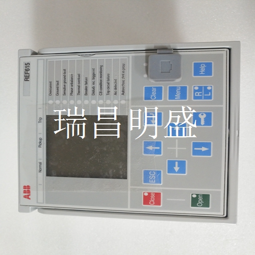
ABB REF615A_1G HAFNAEFCBGC1BQK11G 系统备件
如果未提供其他信息,这些DIP开关应保持在OFF位置。DIP开关7用于配置悬垂模式(更多信息请参见出版物10000071139),DIP开关8用于重置默认配置。一旦更改,DIP开关设置仅在电源循环后才能识别。表15详细说明了I/O板的DIP开关设置。有关所列功能的更多信息,请参阅编程指南。默认参数表16列出了前面讨论的每个参数的默认值,可以通过使用DIP开关阵列S1上的开关8进行重置,然后进行电源循环。示教过程示教功能允许您通过使用I/O扩展PCB上的按钮配置多个功能的参数。以下各节详细介绍了可教给传感器的参数以及与此程序相关的步骤。在开始此过程之前:•确认灯阵列安装在目标应用中。•在示教过程的任何阶段关闭电源将取消该过程并恢复先前存储的值。•重复按下示教按钮,直到示教过程完成且状态指示器D14熄灭(且不闪烁),也可以恢复先前的值。•通过使用DIP开关阵列S1上的开关8,可以重置默认参数。•默认情况下,每个区域配置为光阵列中光束数量的1/4。分步示教功能指南1.开始示教按住示教按钮约5秒,直到状态指示器D14开始每3秒闪烁一次,这表明装置处于示教模式。2.遮蔽光束检查以确认应用程序中通常会中断(遮蔽)的光束是否被中断。再次短按示教按钮-状态指示器D14现在大约每3秒闪烁两次,这表示识别到任何中断(消隐)的光束。覆盖梁始终被忽略。在空白光束区域中不能定义其他光束或区域。只能在检测区域上方和下方定义消隐光束,而不能在传感区域之间定义消隐波束。
If no additional information is provided, these DIP switches should remain in the OFF position. DIP switch 7 is used to configure the drape mode (see publication 10000071139 for more information), and DIP switch 8 is used to reset the default configuration. Once changed, the DIP switch settings are recognized only after a power cycle. Table 15 details the DIP switch settings for the I/O board. Refer to the programming guide for more information on the listed functions. Table 16 of Default Parameters lists the default values of each parameter discussed previously. You can reset it by using switch 8 on DIP switch array S1, and then cycle the power supply. The Teach Process Teach function allows you to configure parameters for multiple functions by using the buttons on the I/O expansion PCB. The following sections detail the parameters that can be taught to the sensor and the steps associated with this procedure. Before starting this process: • Verify that the lamp array is installed in the target application. • Turning off the power at any stage of the teaching process will cancel the process and restore the previously stored values. • Press the teaching button repeatedly until the teaching process is completed and the status indicator D14 goes out (without flashing), and the previous value can also be restored. • The default parameters can be reset by using switch 8 on DIP switch array S1. • By default, each area is configured as 1/4 of the number of beams in the optical array. Step by step teaching function guide 1. Start teaching Press and hold the teaching button for about 5 seconds until the status indicator D14 starts flashing every 3 seconds, which indicates that the device is in teaching mode. 2. Masking beam check to confirm whether the beam that is normally interrupted (masked) in the application is interrupted. Briefly press the Teach button again - the status indicator D14 now flashes approximately twice every 3 seconds, indicating that any interrupted (blanking) beam is recognized. Overlay beams are always ignored. No other beam or area can be defined in the blank beam area. The blanking beam can only be defined above and below the detection area, and cannot be defined between sensing areas.


