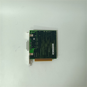
UCD240A101 3BHE022287R0101自动化模块备件
滤波器
相移为0…180°。图14自动化出版物PFLEXRM002DENE2013年8月第1章详细驱动配置和操作速度控制调节器中有一个二阶低通滤波器。该滤波器位于速度误差信号之后。中断频率由参数89[Spd Err Filt BW]设置。中断频率设置为速度环路带宽的五倍(5倍)。该滤波器用于衰减速度环路无法控制的任何高频噪声。超前滞后滤波器PowerFlex 700S包含一个通用超前滞后滤波器。滤波器具有以下拉普拉斯传递函数:Kn是滤波器的增益项,Wn是滤波器频率项。超前滞后滤波器“滞后”当Kn小于1(Kn1)时,超前滞后滤波器作为超前滤波器运行。原始方程被重新写入一个可用于利用导函数的项。Wn在整个方程中被除。开发了两个新术语。
正向路径参数95
[SReg Out Filt Gain]参数96[SReg Out Filt BW]反馈路径参数93[SReg FB Filt Gain]参数94[SReg FB Filt BW]58自动化出版物PFLEXRM002DENE2013年8月第1章详细驱动配置和操作前置项(Wld)用于显示滤波器的前置。滞后项(Wlg)用于显示滤波器的滞后。图17显示了引导函数的伯德图。超前项用于抵消系统中的滞后。速度环路带宽在位置环路中表现为低通滤波器或滞后。超前滤波器可用于消除速度环路滞后,并用更快的滞后代替。图17Kn>1“铅过滤器”在以下示例中:•系统显示为滞后,响应为5 rad/sec。•超前滤波器设置为补偿5 rad/sec响应(Wld=5)•滞后滤波器设置为50 rad/sec反应(Wlg=50)•Kn设置为Wlg/Wld(50/5)=10•Wn设置为Wrg=50 Kn s Wn×+s Wn+Kn s Wn×()+1 s Wn⁄()+1s Wld⁄(wn Wlg=Kn Wlg Wld=自动化出版物PFLEXRM002DENE2013年8月59详细的驱动器配置和操作第1章图18显示了添加超前滞后的结果
wave filter
The phase shift is 0... 180 °. Figure 14 Automation publication PFLEXRM002DENE August 2013 Chapter 1 Detailed Drive Configuration and Operating Speed Control Regulator has a second-order low-pass filter. The filter is located after the speed error signal. The interrupt frequency is set by parameter 89 [Spd Err Filt BW]. The interrupt frequency is set to five times the speed loop bandwidth. This filter is used to attenuate any high-frequency noise that cannot be controlled by the speed loop. The lead lag filter PowerFlex 700S includes a universal lead lag filter. The filter has the following Laplace transfer function: Kn is the gain term of the filter, and Wn is the frequency term of the filter. Lead lag filter "lag" When Kn is less than 1 (Kn1), the lead lag filter operates as a lead filter. The original equation is rewritten to a term that can be used to utilize the derivative function. Wn is divided throughout the equation. Two new terms have been developed.
Forward path parameter 95
[SReg Out Filt Gain] parameter96 [SReg Out Filt BW] feedback path parameter93 [SReg FB Filt Gain] parameter94 [SReg FB Filt BW] 58 automation publication PFLEXRM002DENE, August 2013, Chapter 1, Detailed Drive Configuration and Operation Precedent (Wld) is used to display the prefixes of filters. The hysteresis term (Wlg) is used to display the hysteresis of the filter. Figure 17 shows the Bode diagram of the boot function. The preceding term is used to offset the lag in the system. The speed loop bandwidth is represented as a low-pass filter or hysteresis in the position loop. The leading filter can be used to eliminate the speed loop hysteresis and replace it with a faster hysteresis. Figure 17Kn>1 "Lead filter" in the following example: • The system is displayed as hysteresis, and the response is 5 rad/sec. • The leading filter is set to compensate 5 rad/sec response (Wld=5) • The lagging filter is set to 50 rad/sec response (Wlg=50) • Kn is set to Wlg/Wld (50/5)=10 • Wn is set to Wrg=50 Kn s Wn ×+ s Wn+Kn s Wn × ()+1 s Wn ⁄ ()+1 s Wld ⁄ (wn Wlg=Kn Wlg Wld=Automation publication PFLEXRM002DENE August 59, 2013 Detailed drive configuration and operation Chapter 1 Figure 18 shows the results of adding lead lag


