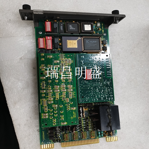
XVC724BE102 3BHE009017R0102机器人备件
通过使用适当的子电路和滤波器设置
至范围内的谐波失真可以保持在以下水平−。在至范围内,−可以实现的谐波抑制。除了睡眠和活动模式,×乘法器还可以设置为就绪模式。就绪模式是睡眠和活动模式之间的混合状态,不传递信号,但允许快速开启。就绪模式下的电流消耗高于睡眠模式,但低于活动模式。就绪模式和活动模式之间的切换时间明显快于从睡眠模式到活动模式。数字步进衰减器尽管的乘法器滤波器块内有一个数字步进衰减器,但它不打算用作输出功率的电平控制。该衰减器用于在进入分路器网络之前降低来自乘法器的谐波含量。数字步进衰减器与频率的建议值如表所示,代表谐波性能与输出功率水平之间的平衡。因此,不建议更改这些值。注意,_的值(指_和_位)对应于最大衰减。低通陷波滤波器在输出之后包括低通斩波滤波器,以帮助在传输所需信号之前减少任何不希望的谐波含量。小于的输出频率得益于启用此滤波器。大于的输出频率必须关闭该滤波器,以减少由于该滤波器引起的任何插入损耗。
位高以启用滤波器
最佳谐波抑制输入频率()输出频率()乘法器滤波器设置乘法器频带_低通陷波滤波器__寄存器值__寄存器值.至.至低频带有效(中高频带就绪)低在.至.至低频带有效至低频带活动(中频和高频带就绪)高开.至.至中频带活动(低频和高频带已就绪)低关.至.至中频带激活(低频和高频带就绪)高开.至.至高频带活动(低和中频带就绪(低频带和中频带就绪)高关_指的是_和_位字段。__指的是寄存器。
By using the appropriate subcircuits and filter settings
The harmonic distortion in the range to can be maintained at the following level −. In the range to, − harmonic suppression that can be achieved. In addition to sleep and activity patterns, × The multiplier can also be set to ready mode. Ready mode is a mixed state between sleep and active mode, which does not transmit signals, but allows quick opening. The current consumption in ready mode is higher than that in sleep mode, but lower than that in active mode. The switching time between ready mode and active mode is significantly faster than from sleep mode to active mode. Digital step attenuator Although there is a digital step attenuator in the multiplier filter block, it is not intended to be used as the level control of the output power. The attenuator is used to reduce the harmonic content from the multiplier before entering the splitter network. The recommended values of digital step attenuator and frequency are shown in the table, representing the balance between harmonic performance and output power level. Therefore, changing these values is not recommended. Note that_ The value of (refers to _ and _ bits) corresponds to the maximum attenuation. The low-pass notch filter includes a low-pass chopper filter after the output to help reduce any unwanted harmonic content before transmitting the desired signal. An output frequency of less than benefits from enabling this filter. The filter must be turned off when the output frequency is greater than to reduce any insertion loss caused by the filter.
Bit height to enable filter
Optimal harmonic suppression Input frequency () Output frequency () Multiplier filter Setting multiplier frequency band_ Low pass notch filter__ Register value__ Register values. to. to low band effective (middle and high frequency band ready) low in. to. to low band effective to low frequency band active (middle and high frequency band ready) high open. to. to medium frequency band active (low and high frequency band ready) low close. to. to medium frequency band active (low and high frequency band ready) high open. to To high band activity (low and intermediate band ready (low and intermediate band ready) high off_ It means_ And_ Bit field__ Refers to registers.


