


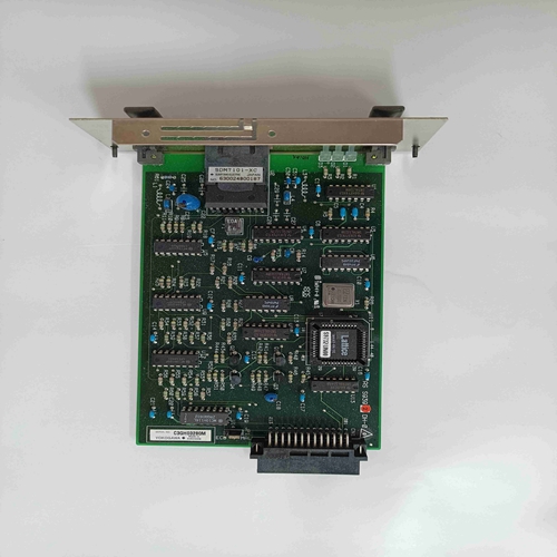
A4H254-8F8T P0973JP模拟量输出模块
关闭电源
锁定/挂牌装置;并等待五分钟以使所有电压放电。打开电源结构的托架门。更换隔离板1.使用仪表测试交流线路、直流母线和隔离板上端子的电压。2.戴上ESD腕带并将其连接到PE母线(装置底部的后接地棒)。3.拆卸Lexan™ 与隔离板隔离。4.断开P1的接地连接、J1的反馈连接、J2的带状电缆以及J7的电流传感器连接(如图1所示)。5.断开接线板TB5和TB6。6.逆时针转动六个安装支架,松开电路板并将电路板拉出。7.从每个接线板上拆下负载电阻器。8.将隔离板放在防静电袋中!注意:如果存在任何电压,请拆下电压源。继续下一步前,再次检查电压。
负载电阻器套件
TB2仅用于B系列RGU(或RGU至交流线路至直流母线至主控制板(J12)至未使用的电流传感器T相负载电阻器(F17、F18、F19)S相负载电阻器*R相负载电阻器至控制电路电路。电流代码电压代码负载电阻器套件编号欧姆%公差类型J N,电流电压系列代码位于主控制板附近的典型RGU铭牌例如,此铭牌显示电流代码L和电压代码C。合适的套件为2364-SDP06A。由于铭牌显示这是一个a系列装置,TB2中不需要电阻器。a系列B出版物2364F-5.13 1999年6月RGU™ 隔离板更换5安装隔离板1.将负载电阻器固定在新板上的端子中(验证透明绝缘层没有进入端子)。拧紧至6 lb in(0.7 N-m)。注:TB2仅用于B系列RGU(见数据铭牌)。2.将电路板放在六个支架上并固定电路板。3.将端子块TB5和TB6连接至隔离板。接线板必须牢固地压入适当的插座中。4.将反馈连接连接到J1,将带状电缆连接到J2,将电流传感器连接到J7,将PE地线连接到P1
Turn off the power
Lock out/tag out device; Wait five minutes to discharge all voltages. Open the bay door of the power structure. Replace the isolation board 1. Use the instrument to test the voltage of AC lines, DC buses and terminals on the isolation board. 2. Wear the ESD wrist strap and connect it to the PE bus (the rear ground bar at the bottom of the unit). 3. Remove Lexan ™ Isolate from the isolation plate. 4. Disconnect P1's grounding connection, J1's feedback connection, J2's ribbon cable and J7's current sensor connection (as shown in Figure 1). 5. Disconnect terminal blocks TB5 and TB6. 6. Rotate the six mounting brackets anticlockwise, release the circuit board and pull it out. 7. Remove the load resistor from each terminal block. 8. Put the isolation plate in the anti-static bag! NOTE: If any voltage is present, remove the voltage source. Check the voltage again before proceeding to the next step.
KIT-LOAD RESISTOR
TB2 is only used for B series RGU (or RGU to AC line to DC bus to main control board (J12) to unused current sensor T phase load resistor (F17, F18, F19) S phase load resistor * R phase load resistor to control circuit circuit. Current Code Voltage Code Load Resistor Kit Number Ohm% Tolerance Type J N, Current Voltage Series Code Typical RGU nameplate located near the main control panel For example, this nameplate shows current code L and voltage code C. The appropriate kit is 2364-SDP06A. Since the nameplate shows that this is a series a device, no resistor is required in TB2. A Series B Publication 2364F-5.13 June 1999 RGU ™ Replace the isolation board 5 Install the isolation board 1. Fix the load resistor in the terminal on the new board (verify that the transparent insulating layer does not enter the terminal). Tighten to 6 lb in (0.7 N-m). Note: TB2 is only used for B series RGUs (see data nameplate). 2. Place the circuit board on the six brackets and fix the circuit board. 3. Connect terminal blocks TB5 and TB6 to the isolation board. The terminal block must be firmly pressed into the appropriate socket. 4. Connect the feedback connection to J1, the ribbon cable to J2, the current sensor to J7, and the PE ground wire to P1
")
")
")

