


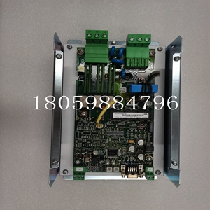
XDD501A101 3BHE036342R0101 DCS控制模块
直流母线电源单元
更换套件说明RGU™ 主控制板更换固件版本3.01内容本文档介绍了如何卸下和更换再生直流母线电源单元(RGU)中的主控制板。本套件包含的内容使用下表,确认您已收到套件中的相应项目:其他需要的项目在开始之前,请确保您还拥有以下工具:•测量电压–拆卸、松开、,和紧固螺钉(包括端子螺钉)–扭矩螺钉(4至14 lb in/0.5至1.5 N-m)•文档:–您的驱动系统示意图–出版物2364F-5.01,再生直流母线电源单元(RGU)–用户手册对于该部分:您应该收到以下数量:主控板1 ESD腕带1出版物2364F-5.12 1999年3月2 RGU™ 主控制板更换固件版本3.01安全注意事项在维修RGU或驱动系统时,以下一般注意事项适用:特殊说明重要:您需要重新使用从装置上拆下的零件。
将零件按拆下的顺序放在干净的表面上
重要提示:新的主控制板可能不包括与现有板相同的参数设置。如有必要,在更换主控制板之前记录参数设置!注意:只有熟悉驱动系统、系统中使用的产品和相关机械的人员才能计划或实施系统的安装、启动和未来维护。不遵守规定可能导致人身伤害和/或设备损坏。注意:根据ANSI/NFPA 70E第二部分的要求,确认所有交流和直流电源均已断电、锁定或挂牌。注意:系统可能包含储能装置。为避免触电危险,在尝试维修、修理或拆卸驱动系统或其部件之前,请确认电容器上的所有电压已放电。只有在您有资格且熟悉固态控制设备和出版物NFPA 70E中的安全程序的情况下,才应尝试本手册中的程序。
DC bus power supply unit
Replacement kit description RGU ™ Main Control Board Replacement Firmware Version 3.01 Content This document describes how to remove and replace the main control board in the Regenerative DC Bus Power Supply Unit (RGU). The contents of this kit use the following table to confirm that you have received the corresponding items in the kit: Before starting other required items, please ensure that you also have the following tools: • Measure the voltage – Remove, loosen,, and tighten screws (including terminal screws) – Torque screws (4 to 14 lb in/0.5 to 1.5 N-m) • Document: – Schematic diagram of your drive system – Publication 2364F-5.01, Regenerative DC Bus Power Supply Unit (RGU) – User's Manual For this section: You should receive the following quantities: Main Control Panel 1 ESD Wrist Strap 1 Publication 2364F-5.12 March 1999 2 RGU ™ Main control board replacement firmware version 3.01 Safety precautions When repairing the RGU or drive system, the following general precautions apply: Special instructions Important: You need to reuse the parts removed from the device.
Place the parts on a clean surface in the order they were removed
Important: The new main control board may not include the same parameter settings as the existing board. If necessary, record the parameter settings before replacing the main control board! Note: Only personnel familiar with the drive system, products used in the system and related machinery can plan or implement the installation, startup and future maintenance of the system. Failure to comply may result in personal injury and/or equipment damage. NOTE: Confirm that all AC and DC power supplies are de energized, locked out, or tagged out in accordance with ANSI/NFPA 70E, Part II. Note: The system may contain energy storage devices. To avoid the danger of electric shock, before attempting to repair, repair or disassemble the drive system or its components, please confirm that all voltages on the capacitor have been discharged. The procedures in this manual should only be attempted if you are qualified and familiar with the safety procedures in solid state control equipment and publication NFPA 70E.
")
")

