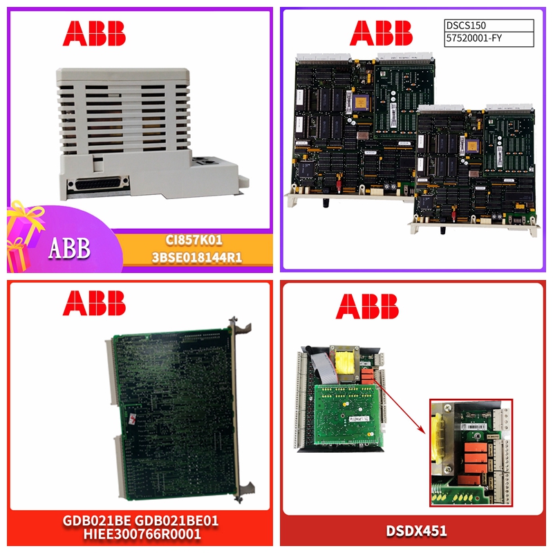
VMIACC-5595-208工控备件机器人模块
安装技术
较高的电感器值将有助于消除此问题。热考虑应注意确保最坏情况下的输入电压和负载电流条件不会导致模具温度过高。R封装的典型热阻为30°C/W,T7封装的热阻为50°C/W。但这些数值会因安装技术(铜面积、气流等)而异。热量通过接线片从封装传递。平均电源电流(包括驱动器电流)为:IIN=4.5mA+DC(ISW/45)ISW=开关电流DC=开关占空比开关功耗由以下公式给出:PSW=(ISW)2(RSW)(DC)RSW=输出开关导通电阻管芯的总功耗为电源电流乘以电源电压之和,加上开关电源:PD(TOTAL)=(IIN)(VIN)+PSW表面贴装散热器可用,可将封装热阻降低两三倍。一家制造商Wakefield Engineering为R封装提供表面安装散热器
电感器的范围
选择电感器对于大多数应用,电感器的范围为2.2µH至22µH。选择较低的值以减小电感器的物理尺寸。更高的值允许更多的输出电流,因为它们减少了功率开关所看到的峰值电流,功率开关具有6A限制。较高的值也会降低输入纹波电压并降低铁芯损耗。在选择电感器时,您需要考虑最大负载电流、铁芯和铜损耗、允许的组件高度、输出电压纹波、EMI、电感器中的故障电流、饱和,当然还有成本。建议采用以下程序来处理这些有点复杂和冲突的要求。1.假设升压转换器的平均电感器电流等于负载电流乘以VOUT/VIN,并决定电感器是否必须承受连续过载条件。例如,如果最大负载电流下的平均电感器电流为3A,则3A电感器可能无法承受连续6A过载条件。还要注意,升压转换器没有短路保护,在输出短路条件下,电感器电流仅受输入电源的可用电流限制。
Installation technology
Higher inductor values will help eliminate this problem. Thermal considerations should take care to ensure that the worst case input voltage and load current conditions do not cause excessive mold temperatures. The typical thermal resistance of R package is 30 ° C/W, and that of T7 package is 50 ° C/W. However, these values will vary depending on the installation technology (copper area, airflow, etc.). Heat is transferred from the package through the lugs. The average power supply current (including driver current) is: IIN=4.5mA+DC (ISW/45) ISW=switching current DC=switching duty cycle Switching power consumption is given by the following formula: PSW=(ISW) 2 (RSW) (DC) RSW=total power consumption of output switch on resistance tube core is the sum of power supply current times power supply voltage, plus switching power supply: PD (TOTAL)=(IIN) (VIN)+PSW surface mount radiator is available, which can reduce the package thermal resistance by two or three times. Wakefield Engineering, a manufacturer, provides surface mounted radiators for R encapsulation
Inductor range
Select inductors For most applications, inductors range from 2.2 µ H to 22 µ H. Select a lower value to reduce the physical size of the inductor. Higher values allow more output current because they reduce the peak current seen by the power switch, which has a 6A limit. Higher values also reduce the input ripple voltage and core loss. When selecting inductor, you need to consider the maximum load current, core and copper loss, allowable component height, output voltage ripple, EMI, fault current in inductor, saturation, and of course cost. The following procedures are recommended to address these somewhat complex and conflicting requirements. 1. Assume that the average inductor current of the boost converter is equal to the load current multiplied by VOUT/VIN, and decide whether the inductor must withstand continuous overload conditions. For example, if the average inductor current at the maximum load current is 3A, the 3A inductor may not be able to withstand a continuous 6A overload condition. Also note that the boost converter has no short-circuit protection. Under the output short-circuit condition, the inductor current is limited only by the available current of the input power supply.


