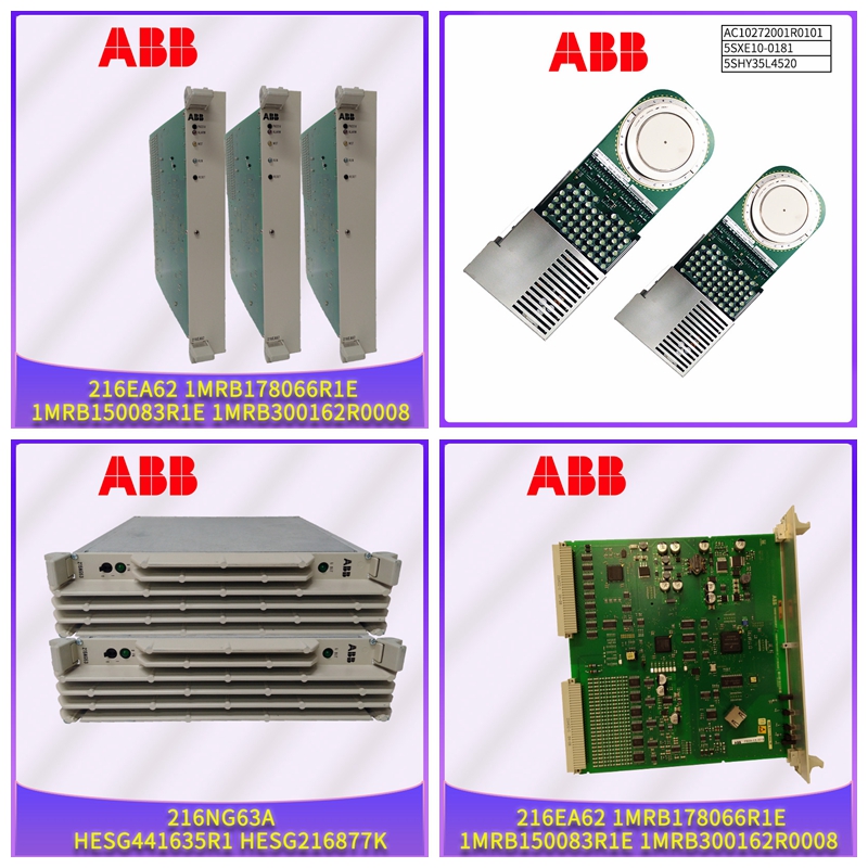
70PR05B-ES模拟量输入模块
线路终端
下拉上拉平衡对从设备1例如,WaterMaster FEX100–MOD从设备n公共D1 D0 D D R R R线路5 V最多31个从设备主电缆属性必须限制中继电缆的端到端长度。最大长度取决于波特率、电缆(仪表、电容或特性阻抗)、菊花链上的负载数量和网络配置(2线或4线)。对于9600波特率和AWG26(或更宽)仪表,最大长度为1000米(3280英尺)。当4线电缆用作2线电缆系统时,最大长度必须除以2。分接电缆必须短,不得超过20米(65.6英尺)。如果一个多端口抽头与n个衍生产品一起使用,每个衍生产品的最大长度必须为40米(131英尺)除以n。RS485系统的最大串行数据传输线长度为1200米(3937英尺)。可使用的电缆长度由电缆类型决定,通常:•最长6 m(19.7 ft.)–标准屏蔽或双绞线电缆。•高达300米(984英尺)–双绞线,带整体箔屏蔽和整体加蔽线–例如Belden 9502或同等产品。•高达1200米(3937英尺)–双绞线,带单独的箔屏蔽和整体加蔽线–例如Belden 9729或同等产品。5类电缆可用于RS485-MODBUS,最大长度为600米(1968英尺)。对于RS485系统中使用的平衡对,尤其是对于19200和更高的波特率,优选值高于100W的特性阻抗。
安装要求本节旨在概述流量计的安装。有关安装要求、技术信息以及健康和安全预防措施,请参阅用户指南OI/FEF/FEV/FEW–EN。打开流量计包装起吊流量计时,必须小心使用流量计主体下提供的吊钩或吊索。
传感器电缆
切勿使用传感器电缆的端子接线盒起吊,否则会造成损坏并使保修失效。吊索角度<90°接地流量计传感器必须与上游和下游管道交叉连接。出于技术原因,该电位应与计量流体的电位相同。通过安装2个流体接触环(用于接地)实现流体连接。流体接触环安装必须遵守下面所示的安装条件,以获得最佳操作效果。传感器管必须始终完全充满。流向必须与标识牌相对应。该装置测量两个方向的流量。正向流量是出厂设置。装置安装时必须无机械张力(扭转、弯曲)。如果需要,支撑管道。支架法兰密封件必须由适用于流体和流体温度的兼容材料制成(如需要)。20°C(–4°F)最低70/130°C(158/266°F)最高密封不得伸入流动区域,因为可能的湍流会影响装置精度。安装与管道尺寸相同的垫圈垫圈20 WATERMASTER电磁流量计| DS/WM-EN REV.Y-…安装要求管道不得对设备施加任何不允许的力和扭矩,如振动。流量计在安装过程中不得受到任何局部加热;注意记住这是一个测量仪器。流量计不得暴露在阳光直射下,或在必要时提供适当的防晒保护。流量计的电缆应整齐安装或安装在导管内,松动或导管应在接线盒高度以下呈u形,以允许水流出,避免毛细管作用进入流量计传感器。确保通过管道的最大干固体含量为6%–对于更高的干固体含量,请参考ABB的ProcessMaster系列。电极轴电极轴应尽可能水平,或与水平线成45°角。上游和下游管段最大45°。计量原理允许流量分布。•尽可能不要在流量计传感器的正前方安装配件(例如歧管、阀门)。•蝶阀的安装应确保阀板不会伸入流量计传感器。•阀门或其他关闭部件应安装在下游管段。经验表明,在大多数安装中,上游直管段3 x DN长和下游直管段2 x DN长通常就足够了。在可能的情况下,我们建议采用5 x DN直上游和2 x DN直下游的条件。对于缩径流量计(FER),通常不需要这些直管段。5 x DN(FEW,FEF)0 x DN(FER)5 x DN
Line terminal
Pull down and pull up the balanced pair slave device 1 For example, WaterMaster FEX100 – MOD slave device n Common D1 D0 D D R R R R Line 5 V Up to 31 slave device master cable attributes must limit the end-to-end length of the trunk cable. The maximum length depends on the baud rate, the cable (instrument, capacitance or characteristic impedance), the number of loads on the daisy chain, and the network configuration (2-wire or 4-wire). For 9600 baud rate and AWG26 (or wider) meters, the maximum length is 1000 meters (3280 feet). When 4-wire cables are used as 2-wire cable systems, the maximum length must be divided by 2. The tap cable must be short and not exceed 20 meters (65.6 feet). If a multi port tap is used with n derivatives, the maximum length of each derivative must be 40 meters (131 feet) divided by n. The maximum serial data transmission line length of RS485 system is 1200 meters (3937 feet). The length of cable available depends on the type of cable, typically: • Up to 6 m (19.7 ft.) – standard shielded or twisted pair cable. • Up to 300 meters (984 feet) – twisted pair with integral foil shield and integral drain wire – e.g. Belden 9502 or equivalent. • Up to 1200 m (3937 ft) – twisted pair with separate foil shield and integral drain wire – e.g. Belden 9729 or equivalent. Category 5 cable can be used for RS485 MODBUS with a maximum length of 600 meters (1968 feet). For balanced pairs used in RS485 systems, especially for 19,200 and higher baud rates, a characteristic impedance higher than 100W is preferred.
Installation Requirements This section is intended to outline the installation of flow meters. For installation requirements, technical information and health and safety precautions, refer to the user guide OI/FEF/FEV/FEW – EN. When opening the flowmeter package to lift the flowmeter, be careful to use the hook or sling provided under the flowmeter body.
Sensor cable
Do not use the terminal box of the sensor cable for lifting, otherwise it will cause damage and invalidate the warranty. The flowmeter sensor with sling angle<90 ° must be cross connected with the upstream and downstream pipelines. For technical reasons, this potential should be the same as that of the metered fluid. The fluid connection is achieved by installing 2 fluid contact rings (for grounding). The installation of the fluid contact ring must comply with the installation conditions shown below for optimal operation. The sensor tube must always be fully filled. The flow direction must correspond to the signboard. The device measures the flow in both directions. The positive flow is factory set. The device must be installed without mechanical tension (twisting, bending). If necessary, support the pipe. The support flange seal must be made of a compatible material suitable for the fluid and fluid temperature, if required. The 20 ° C (– 4 ° F) minimum 70/130 ° C (158/266 ° F) maximum seal must not protrude into the flow area because possible turbulence can affect the accuracy of the unit. Install the gasket 20 WATERMASTER electromagnetic flowmeter | DS/WM-EN REV. Y -... with the same size as the pipe. The installation requires that the pipe shall not exert any impermissible force and torque on the equipment, such as vibration. The flowmeter shall not be subject to any local heating during installation; Remember that this is a measuring instrument. The flowmeter shall not be exposed to direct sunlight or provided with appropriate sun protection when necessary. The cables of the flowmeter shall be neatly installed or installed in the conduit. Loose or the conduit shall be U-shaped below the height of the junction box to allow water to flow out and prevent capillary action from entering the flowmeter sensor. Ensure that the maximum dry solids content through the pipeline is 6% – for higher dry solids content, please refer to ABB's ProcessMaster series. Electrode axis The electrode axis should be as horizontal as possible or at an angle of 45 ° to the horizontal line. 45 ° maximum for upstream and downstream pipe sections. The metering principle allows flow distribution. • Try not to install accessories (such as manifold and valve) directly in front of the flowmeter sensor. • The butterfly valve shall be installed so that the valve plate does not protrude into the flowmeter sensor. • Valves or other closing components shall be installed in the downstream pipe section. Experience has shown that in most installations, 3 x DN of the upstream straight section and 2 x DN of the downstream straight section are usually sufficient. Where possible, we recommend 5 x DN straight upstream and 2 x DN straight downstream. For reduced diameter flowmeters (FER), these straight pipe sections are usually not required. 5 x DN(FEW,FEF)0 x DN(FER)5 x DN


