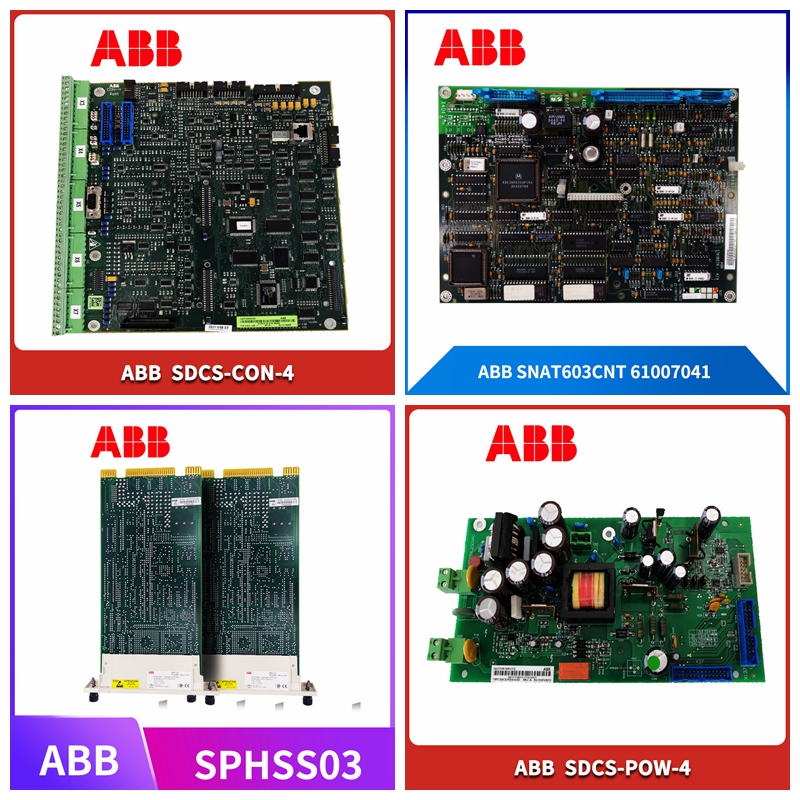
工控备件6MBI450U-120A-05AGDR-71C
变送器连接变送器端子
连接概述本节旨在概述流量计的安装。有关安装要求、技术信息以及健康和安全预防措施,请参阅用户指南OI/FET100–EN。交流/直流电源端子输出连接测试点传感器电缆端子输出连接端子内部接地(替代PE)传感器电缆输出连接外部接地输出连接背板内部接地**对于阴极保护系统(或如果变送器外壳没有接地螺钉),将加蔽线连接到端子SCR。连接电缆前的电缆准备要求见上文**屏蔽线(用D1/TFE–橙色和D2–黄色的屏蔽线缠绕)将电缆切割至70 mm(2.75 in.)将电缆切至60 mm(2.35 in.)。)M1棕色M2红色D1/TFE橙色SCR屏幕D2黄色3绿色(套筒)S2蓝色(屏幕)E2蓝色(信号)E1紫色(信号)S1紫色(屏幕)变送器接线盒处的传感器电缆连接-远程变送器WATERMASTER电磁流量计| DS/WM-EN REV。Y 13电源连接AC电源电源指示灯*AC保险丝F1 250 mA T型(供应商见下表)AC电源通过合适的隔离器和保险丝>4 mm2(4 mm2(<10 AWG)铜线DC(或低压AC)电源通过合适隔离器与保险丝变送器标签外部接地螺钉内部接地螺钉*保险丝供应商保险丝零件号ABB B20412 Bussmann BK/ETF 2AWickmann 19372 K2A红色、黑色、绿色/黄色直流(和低压交流)电源连接14 WATERMASTER电磁流量计| DS/WM-EN REV.Y-…变送器连接配置DIP开关变送器底板上安装了三个配置DIP交换机。这些出厂设置如下:•远程变送器–全部关闭•集成变送器–SW3开启对于符合MID的流量计,只读/MID保护开关设置为“开启”,以确保流量计不会被篡改。对于01.02.XX之前的HART软件版本,此开关(调试后设置)可防止在任何安全级别通过键盘或总线登录。
PROFIBUS软件版本
从HART软件版本01.03.XX起,对于所有PROFIBUS软件版本,在MID仪表上,所有计量相关参数都被锁定,且在服务级别无法访问。标准和高级用户级参数仍可通过HMI或总线进行修改。配置DIP开关OFF ON SW3 SW2 SW1 DIP开关功能SW1–只读/MID保护SW2–(未来产品)SW3–内部传感器存储器配置DIP切换变送器模块识别注释。如果变送器模块标签上没有规定,通信总线类型为HART FEX100。PROFIBUS FEX100-DP变型变送器模块标签示例如下所示。PROFIBUS FEX-100P标签交流转换器模块上的黑色标签直流(和低压交流)转换器模块上红色标签变送器模块标识WATERMASTER电磁流量计| DS/WM-EN REV。Y 15-输出连接频率输出XX XX XX 42 41 51 61 52 62端子连接ID为HART-/PROFIBUS变量相关COM DO1 DO2 PLC或数据记录器PLC/数据记录器连接注。数字输出DO1和DO2对极性敏感。这些输出的公共(负)连接被指定为“COM”。 向流量输出(DO1)计数器/累加器反向流量输出(DO2)计数器/加法器直流电源和/或机电连接1 2 3 3 4 5 1 2 3 6 6 XX XX 42 42 51 61 52 62–+–+COM DO1 DO2正向流量输出(DO1电子计数器连接报警输出终端连接ID为HART-/PROFIBUS-/MODBUS-变量相关 电源喇叭报警1报警2铃声和/或注释。•正常报警/逻辑输出来自DO3(端子61)。如果需要,DO1(41)和DO2(51)也可以配置为警报,但如机电连接和遥测/电子计数器连接所示,则不能作为频率/脉冲输出。•钟声和喇叭仅作为示例。可以使用任何合适的报警装置(例如灯、警报器、蜂鸣器等 定时器开关直流电源报警1报警2继电器和/或注释。继电器和定时器开关仅供示例
Transmitter connection transmitter terminal
Connection Overview This section is intended to provide an overview of the installation of the flowmeter. For installation requirements, technical information and health and safety precautions, refer to the user guide OI/FET100 – EN. AC/DC power supply terminal output connection Test point Sensor cable terminal output connection terminal Internal grounding (instead of PE) Sensor cable output connection External grounding Output connection Backplane internal grounding * * For cathodic protection system (or if the transmitter housing has no grounding screw), connect the shielded wire to the terminal SCR. For cable preparation requirements before cable connection, see the above * * shield wire (twisted with D1/TFE – orange and D2 – yellow shield wire) to cut the cable to 70 mm (2.75 in.) and cut the cable to 60 mm (2.35 in.) M1 brown M2 red D1/TFE orange SCR screen D2 yellow 3 green (sleeve) S2 blue (screen) E2 blue (signal) E1 purple (signal) S1 purple (screen) sensor cable connection at the transmitter junction box - remote transmitter WATERMASTER electromagnetic flowmeter | DS/WM-EN REV. Y 13 Power supply connection AC power supply indicator * AC fuse F1 250 mA Type T (see the table below for the supplier) AC power supply through appropriate isolator and fuse>4 mm2 (4 mm2 (<10 AWG) copper wire DC (or low-voltage AC) power supply through appropriate isolator and fuse transmitter label External grounding screw Internal grounding screw * Fuse supplier fuse part number ABB B20,412 Bussmann BK/ETF 2AWickmann 19,372 K2A Red, black Green/yellow DC (and low-voltage AC) power connection 14 WATERMASTER electromagnetic flowmeter | DS/WM-EN REV. Y -... transmitter connection configuration DIP switch Three configuration DIP switches are installed on the transmitter backplane. These factory settings are as follows: • Remote transmitter – All OFF • Integrated transmitter – SW3 ON For MID compliant flowmeters, the read-only/MID protection switch is set to "ON" to ensure that the flowmeter will not be tampered with. For HART software versions prior to 01.02.XX, this switch (set after debugging) prevents logging in through the keyboard or bus at any security level.
PROFIBUS software version
Since HART software version 01.03.XX, for all PROFIBUS software versions, all measurement related parameters on the MID instrument are locked and cannot be accessed at the service level. Standard and advanced user level parameters can still be modified through HMI or bus. Configure DIP switch OFF ON SW3 SW2 SW1 DIP switch function SW1 – Read only/MID protection SW2 – (future product) SW3 – Internal sensor memory configuration DIP switching transmitter module identification note. If not specified on the transmitter module label, the communication bus type is HART FEX100. An example of a PROFIBUS FEX100-DP variant transmitter module label is shown below. PROFIBUS FEX-100P label Black label on the AC converter module Red label on the DC (and low-voltage AC) converter module Transmitter module identification WATERMASTER electromagnetic flowmeter | DS/WM-EN REV. Y 15 Output connection Frequency output XX XX 42 41 51 61 52 62 Terminal connection ID is HART -/PROFIBUS variable related COM DO1 DO2 PLC or Datalogger PLC/Datalogger connection note. The digital outputs DO1 and DO2 are polarity sensitive. The common (negative) connection of these outputs is specified as "COM". To the flow output (DO1) counter/accumulator negative flow output (DO2) counter/adder DC power supply and/or electromechanical connection 1 2 3 3 4 5 1 2 3 6 XX XX 42 42 51 61 52 62 –+–+COM DO1 DO2 forward flow output (DO1 electronic counter is connected to the alarm output terminal, and the connection ID is HART -/PROFIBUS -/MODBUS - variable related power supply horn alarm 1 alarm 2 bell and/or note. • Normal alarm/logic output is from DO3 (terminal 61). If required, DO1 (41) and DO2 (51) can also be configured as alarms, but they cannot be output as frequency/pulse as shown in electromechanical connection and telemetry/electronic counter connection. • Bells and horns are examples only. Any suitable alarm device (such as lamp, alarm, buzzer, etc.) can be used to switch the DC power alarm 1 alarm 2 relay and/or note. Relay and timer switches are examples only


