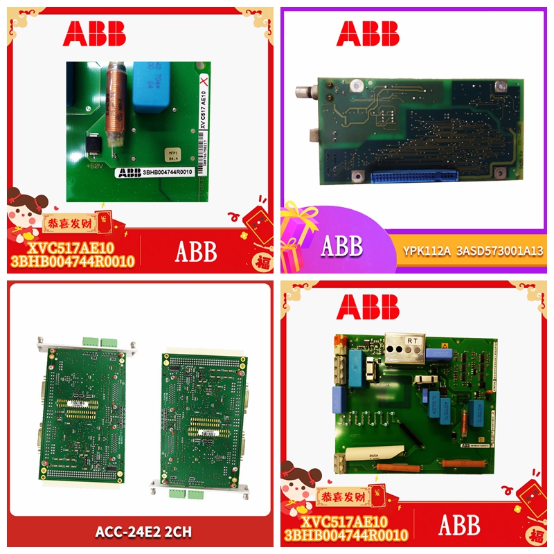
5SHY35L4520自动化工控模块
输入通道使用
块操作这些块有四个独立输入和两个独立输出。输入输入通道使用电压到频率转换器和计数器将模拟电流转换为数字值。该模块将数字值转换为工程单位值,并提供给CPU。EXC 24VDC P.S处理器16位计数器V至F光电隔离。100 COM GND外壳接地47 IN滤波器每个输入都有一个24伏电流回路电源,能够提供25毫安的电流。每个输入都与块上的所有其他电路隔离。输入精度为0.1%。输入转换时间可在16至400ms之间选择。分辨率随着转换时间的延长而增加。输入分辨率为1mA,转换时间为200ms。输出两个独立的输出电路彼此和BSM输出在电气上共用,但与块上的所有其他电路隔离。输出电流回路的电源由模块提供。输出通道使用双12位数模转换器,可以独立控制0mA至24mA的电流。输出分辨率为6mA。24VDC P.S处理器16位计数器V至F光电隔离。反馈放大器。电流传感器电流控制器D/A反馈12位D至A处理器光电数据控制隔离。RTN GND外壳接地BSM开关15VDC 15VDC OUT BSMBSM+两个额外的A至D通道用于在可编程稳定时间后检查两个输出通道。如果来自这些通道的反馈与250mA内的指令值不匹配,则块指示故障。诊断_块的高级诊断提供以下信息。可以从手持监视器或CPU清除故障信息。高报警:输入超过其高报警极限低报警:输入低于其低报警极限开路:输入电流低于2mA输入超范围:信号超过25mA输入欠范围:电流为负或0 mA。
输出超范围:
指令输出超过24mA输出欠范围:指令输出小于0 mA。输入反馈错误:接线错误或硬件故障。注:如果为电路选择的输出反馈时间太短,可能会报告干扰诊断。如果发生这种情况,请增加反馈时间或禁用输出反馈测试。注:如果块在4-20mA范围外使用,如果命令输出值很低,可能会报告错误的输出反馈诊断。当指令输出小于1mA时,可以禁用反馈数据检查,当指令输出大于1mA时可以重新启用反馈数据检查。配置首先,必须使用手持监视器配置块:输入其设备号(串行总线地址)。输入其参考号(仅适用于IC600和IC550系列PLC)。注:如果块配置为离线,则必须正确接地,并在其串行1和串行2端子上安装75欧姆电阻器。有关说明,请参阅离散和模拟I/O块用户手册。其余功能可以使用手持监视器进行配置,也可以通过从主机向块发送写入配置数据报进行配置。功能电路/块工厂设置选择设备号块null 0到31(必须选择)参考地址块无取决于主机CPU类型波特率,Kbd块153.6 std 153.6 stt,153.6 ext,76.8,38.4报告故障电路是/否通道激活电路激活激活/非激活输入缩放电路1µA每eu+/-32767 eng单元0至+25000µA输出缩放电路1μA每eu+/-327677 eng单元1至+24000µA输入转换时间块400ms 16至400ms低报警电路0+/-32768 eng单元高报警电路+25000+/-3277 eng.单元输出反馈启用电路是/不输出反馈时间电路0ms 0至255ms保持最后状态电路否是/否输出默认电路4000+/-32767 eng.units BSM Present Block no是/否BSM Controller Block no yes/no输出默认时间块2.5秒2.5/10秒CPU冗余块无/备用配置保护块禁用启用禁用
Input Channel Usage
Block Operation These blocks have four independent inputs and two independent outputs. Input input channels use voltage to frequency converters and counters to convert analog currents to digital values. This module converts numerical values into engineering unit values and provides them to the CPU. EXC 24VDC P. S processor 16 bit counter V to F photoelectric isolation. The 100 COM GND enclosure grounded 47 IN filter has a 24 volt current loop power supply for each input, capable of supplying 25 mA. Each input is isolated from all other circuits on the block. The input accuracy is 0.1%. The input conversion time can be selected from 16 to 400ms. The resolution increases with the extension of the conversion time. The input resolution is 1mA, and the conversion time is 200ms. Two independent output circuits are electrically shared with each other and BSM output, but isolated from all other circuits on the block. The power supply of the output current loop is provided by the module. The output channel uses a dual 12 digit analog converter, which can independently control the current from 0mA to 24mA. The output resolution is 6mA. 24VDC P. S processor 16 bit counter V to F photoelectric isolation. Feedback amplifier. The current sensor current controller D/A feedback 12 bit D to A processor photoelectric data control isolation. RTN GND case grounding BSM switch 15VDC 15VDC OUT BSMBSM+two additional A to D channels are used to check the two output channels after the programmable stabilization time. If the feedback from these channels does not match the command value within 250mA, the block indicates a fault. Diagnosis_ The advanced diagnostics for the block provide the following information. The fault information can be cleared from the hand-held monitor or CPU. High alarm: input exceeds its high alarm limit Low alarm: input is lower than its low alarm limit Open circuit: input current is lower than 2mA Input out of range: signal exceeds 25mA Input out of range: current is negative or 0 mA.
Output out of range:
The instruction output exceeds the 24mA output under range: the instruction output is less than 0 mA. Input feedback error: wiring error or hardware failure. Note: If the output feedback time selected for the circuit is too short, interference diagnosis may be reported. If this happens, increase the feedback time or disable the output feedback test. Note: If the block is used outside the 4-20mA range, if the command output value is very low, incorrect output feedback diagnosis may be reported. When the command output is less than 1mA, the feedback data check can be disabled. When the command output is greater than 1mA, the feedback data check can be re enabled. To configure, you must first use the handheld monitor configuration block: enter its device number (serial bus address). Enter its reference number (for IC600 and IC550 series PLCs only). Note: If the block is configured offline, it must be properly grounded and a 75 ohm resistor must be installed on its Serial 1 and Serial 2 terminals. For instructions, refer to the Discrete and Analog I/O Block User Manual. Other functions can be configured using a handheld monitor or by sending a write configuration datagram from the host to the block. Function circuit/block Factory setting Select device number block null 0 to 31 (must be selected) Reference address block does not depend on host CPU type baud rate, Kbd block 153.6 std 153.6 stt, 153.6 ext, 76.8, 38.4 Report fault circuit Yes/No Channel active circuit Active/inactive Input scaling circuit 1 µ A per eu+/- 32767 eng Unit 0 to+25000 µ A Output scaling circuit 1 μ A Each eu+/- 327677 eng unit 1 to+24000 µ A input conversion time block 400ms 16 to 400ms low alarm circuit 0+/- 32768 eng unit high alarm circuit+25000+/- 3277 eng. Unit output feedback enable circuit yes/no output feedback time circuit 0ms 0 to 255ms keep the last state circuit yes/no output default circuit 4000+/- 32767 eng.units BSM Present Block no yes/no BSM Controller Block no yes/no output default time block 2.5 seconds 2.5/10 seconds CPU redundancy block no /Standby configuration protection block disable enable disable


