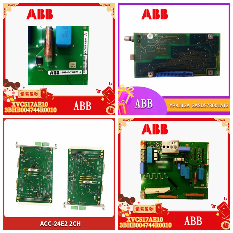
3HNM07686-1工控备件
统计总显示
即发送至本电站用户参考指南 32 System Diagnostics©2014 Molex股份有限公司工业产品事业部综合产品部的未经请求的消息文件版本:1.0,文件#:715-0109,模板版:1.1,模板35;:QMS-06-045使用,复制或披露本文件或其中包含的任何信息均受本文件第ii页的限制。用户参考指南从属功能33©2014 Molex股份有限公司工业产品业务部,集成产品部文件版本:1.0,文件#:715-0109,模板版本:1.1,模板35;:QMS-06-045本文件或其中包含的任何信息的使用、复制或披露受本文件第二页的限制。6从机功能章节章节:•从机输入/输出接口•寄存器定义和布局•输入/输出表添加/修改•配置表添加•从机配置和编程用户参考指南 34从机功能©2014 Molex股份有限公司工业产品业务部,集成产品部文档版本:1.0,文档#:715-0109,模板版本:1.1,模板编号:QMS-06-045使用、复制或披露本文件或其中包含的任何信息均受本文件第ii页的限制。6.1从I/O接口具体而言,I/O接口由以下区域组成:6.1.2附加配置文件的接口图像表11:附加配置文件区域的ControlLogix从接口图像描述区域布局含义/描述大小输出区域CMD控制寄存器本地:插槽:O.ModuleControl。CMD_Cntrl向从机发出命令有关详细信息,请参阅命令控制寄存器。1 x 8位更改页面寄存器本地:插槽:O.ModuleControl。ChangePage不适用。保留为0.1 x 8位CMD参数本地:插槽:O。ModuleControl CMD_Agument有关所有可用命令,请参阅下面的命令参数寄存器。1 x 8位CMD_Additional_Parameter Local:插槽:O.ModuleControl。CMD_Additional_Parameter不适用。保留为0.1 x8位输出数据区域本地:插槽:O。ProfibusDataOut[0]至本地:插槽:O。ProfibusDataOut[121]对于AOP,PROFIBUS输出数据从标记ProfibusData Out[0]开始。注:不使用ProfibusDataOut[122]–[247]。246 x 16位输入数据区域模块状态寄存器本地:插槽:I.ModuleStat。ModuleStatus有关更多详细信息,请参阅下面的模块状态寄存器。1 x 8位当前页寄存器本地::插槽:I:.ModuleStat。CurrentPage这应始终为0.1 x 8位模块命令应答寄存器本地:插槽:I.ModuleStat。上述CMD参数的CMD_Reply回显。有关详细信息,请参阅命令回复寄存器。
数据区域本地:
1 x 8位保留保留-请勿使用1 x 8比特输入数据区域本地:插槽:I。ProfibusDataIn[0]至本地:插槽:I。ProfibusDataIn[121]PROFIBUS输入区从标记ProfibusData In[0]开始。注:ProfibusDataIn[122]–[247]未使用248 x 16位状态区。此处仅说明从模式的适用寄存器。状态文件中的其他寄存器不适用。卡状态寄存器PfbStatus指示卡的状态。有关详细信息,请参阅卡状态寄存器。1 x 16位区域描述区域布局含义/描述尺寸Profibus固件版本PfbModVer表示Profibus软件版本1 x 16位AOP PfbModVer和ReconfigStatus之间的标签不适用于此模块重新配置状态重新配置状态在RSLogix 5000中打开模块连接时应用配置更改时发送的重新配置消息的状态。1 x 8位AOPReconfigStatus和DiagInd之间的标签不适用于此模块诊断指示DiagInds表示模块正在从Profibus网络获取更新1 x 16位AOP DiagInd和SlvStatus之间的标签并不适用于此模件SlvStatusLocal从机状态寄存器请参阅下面的从机状态以了解更多详细信息1 x 8位SlvError包含错误代码的本地从机错误寄存器。有关详细信息,请参阅下面的从属错误代码。1 x 8位剩余AOP标签不适用于此模块6.1.3通用配置文件的接口图像表12:ControlLogix从接口图像(用于使用INT数据类型的通用配置文件)区域描述区域布局含义/描述大小输出区域CMD控制寄存器(低字节)本地:插槽:O。数据[0]向从属设备发出命令。有关详细信息,请参阅命令控制寄存器。16位CMD参数(低字节)本地:插槽:O。数据[1]有关所有可用命令,请参阅下面的命令参数寄存器。16位输出数据区本地:插槽:O。数据[2]至本地:插槽:O。数据[123]PROFIBUS输出数据开始于字偏移量2.122 x 16位输入数据区域模块状态寄存器(位0-7)本地:插槽:I。数据[0]有关详细信息,请参阅下面的模块状态寄存器。16位模块命令应答寄存器本地:插槽:I。数据[1]上述CMD参数的回声。有关详细信息,请参阅命令回复寄存器。16位输入数据区本地:插槽:I。ProfibusDataIn[2]至本地:插槽:I.ProfProfibusDataIn[123]PROFIBUS输入区从字偏移量2.122 x 16位状态区卡状态寄存器(本地:插槽:S.Data[0])指示卡的状态请参阅卡状态寄存器了解更多详细信息1 x 16位PROFIBUS模块版本(本地:槽:S.Data[1])指示PROFIBUS固件版本1 x 16比特诊断指示(本地:Slot:S.Data[07]表示模块正在从Profibus network 1 x 16位用户参考指南 36 Slave Functionality©2014 Molex股份有限公司工业产品业务部门,集成产品部门文件版本:1.0,文件#:715-0109,模板版本:1.1,模板35;:QMS-06-045使用,复制或披露本文件或其中包含的任何信息均受本文件第ii页的限制。区域描述区域布局含义/描述尺寸重新配置状态(本地:插槽:S.Data[4].8-15)在RSLogix 5000.1 x 8位从机状态(本地:Slot:S.Data[44].00-07本地从机状态寄存器)中模块连接打开时应用配置更改时发送的重新配置消息的状态(本地:插槽:S.Data[44].08-15)包含错误代码的本地从属错误寄存器。有关详细信息,请参阅下面的从属错误代码。1 x 8位
General statistics display
It will be sent to the user reference guide 32 System Diagnostics of the power station © 2014 Molex Co., Ltd. Industrial Products Division Integrated Products Division's unsolicited message file version: 1.0, file #: 715-0109, template version: 1.1, template 35;: QMS-06-045 The use, reproduction or disclosure of this document or any information contained therein is subject to the restrictions of page ii of this document. User Reference Guide Dependent Functions 33 © 2014 Molex Co., Ltd. Industrial Products Business Department, Integrated Products Department Document version: 1.0, Document #: 715-0109, Template version: 1.1, Template 35;: QMS-06-045 The use, reproduction or disclosure of this document or any information contained therein is restricted by the second page of this document. 6 Slave function chapter chapter: • Slave input/output interface • Register definition and layout • Input/output table addition/modification • Configuration table addition • Slave configuration and programming user reference guide 34 Slave function © 2014 Molex Co., Ltd. Industrial Products Business Department, Integrated Products Department Document version: 1.0, Document #: 715-0109, Template version: 1.1, Template number: QMS-06-045 The use, copying or disclosure of this document or any information contained therein are subject to the restrictions of page ii of this document. 6.1 In terms of I/O interface, I/O interface consists of the following areas: 6.1.2 Interface image of additional configuration file Table 11: ControlLogix of additional configuration file area describes the layout meaning/description size of the area from the interface image Output area CMD control register Local: Slot: O ModuleControl。 CMD_ Cntrl issues a command to the slave For more information, see Command Control Registers. 1 x 8-bit change page register Local: Slot: O.ModuleControl. ChangePage is not applicable. Reserved as 0.1 x 8-bit CMD parameter Local: Slot: O. ModuleControl CMD_ Agument For all available commands, see the command parameter register below. 1 x 8-bit CMD_ Additional_ Parameter Local: Slot: O.ModuleControl. CMD_ Additional_ Parameter is not applicable. Reserved as 0.1 x8 bit output data area Local: Slot: O. ProfibusDataOut [0] to local: Slot: O. ProfibusDataOut [121] For AOP, PROFIBUS output data starts from the tag ProfibusData Out [0]. Note: ProfibusDataOut [122] – [247] is not used. 246 x 16 bit Input Data Area Module Status Register Local: Slot: I ModuleStat。 ModuleStatus For more details, see the module status register below. 1 x 8-bit current page register Local:: Slot: I:. ModuleStat. CurrentPage This should always be 0.1 x 8-bit module command reply register Local: Slot: I ModuleStat。 CMD of the above CMD parameters_ Reply echo. For more information, see Command Reply Register.
Data region local:
1 x 8-bit reserved reserved - Do not use 1 x 8-bit input data area Local: Slot: I. ProfibusDataIn [0] to local: Slot: I. ProfibusDataIn [121] The PROFIBUS input field starts with the mark ProfibusData In [0]. Note: ProfibusDataIn [122] – [247] does not use the 248 x 16 bit status area. Only applicable registers of slave mode are described here. Other registers in the status file are not applicable. The card status register PfbStatus indicates the status of the card. For more information, see Card Status Register. 1 x 16 bit area description area layout meaning/description size Profibus firmware version PfbModVer indicates that the label between Profibus software version 1 x 16 bit AOP PfbModVer and ReconfigStatus is not applicable to this module reconfiguration status Reconfiguration status Reconfiguration status The status of the reconfiguration message sent when the configuration change is applied when the module connection is opened in RSLogix 5000. The tag between 1 x 8-bit AOPReconfigStatus and DiagInd is not applicable to this module. Diagnostic indication DiagInds indicates that the module is getting updated tags between 1 x 16 bit AOP DiagInd and SlvStatus from the Profibus network. The tag between 1 x 16 bit AOP DiagInd and SlvStatus is not applicable to this module. See Slave Status below for more details. 1 x 8-bit SlvError contains the local slave error register of the error code. For more information, see Dependent Error Codes below. The 1 x 8-bit remaining AOP tag is not applicable to the 6.1.3 interface image of the general configuration file of this module Table 12: ControlLogix describes the layout meaning of the area from the interface image (for the general configuration file using the INT data type) area/describes the size of the output area CMD control register (low byte) Local: Slot: O. Data [0] sends a command to the slave device. For more information, see Command Control Registers. 16 bit CMD parameter (low byte) Local: Slot: O. Data [1] For all available commands, see the command parameter register below. 16 bit output data area Local: Slot: O. Data [2] to local: Slot: O. Data [123] PROFIBUS output data starts from word offset 2.122 x 16 bit input data area module status register (bits 0-7) Local: slot: I. Data [0] For details, see the module status register below. 16 bit module command response register Local: Slot: I. Data [1] Echo of the above CMD parameters. For more information, see Command Reply Register. 16 bit input data area Local: Slot: I. ProfibusDataIn [2] to local: slot: I.ProfProfibusDataIn [123] PROFIBUS input area Word offset 2.122 x 16 bit status area Card status register (local: slot: S.Data [0]) Indicates card status See card status register for more details 1 x 16 bit PROFIBUS module version (local: slot: S.Data [1]) Indicates PROFIBUS firmware version 1 x 16 bit diagnostic indication (local: Slot: S.Data [07] Indicates that the module is running from the Profibus network 1 x 16 bit user reference guide 36 Slave Functionality © 2014 Molex Co., Ltd. Industrial Product Business Department, Integrated Product Department Document Version: 1.0, Document #: 715-0109, Template Version: 1.1, Template 35;: QMS-06-045 The use, reproduction or disclosure of this document or any information contained therein is subject to the restrictions of page ii of this document. Area description Area layout meaning/description Size reconfiguration status (local: slot: S.Data [4]. 8-15) In RSLogix 5000.1 x 8-bit slave status (local: Slot: S.Data [44]. 00-07 local slave status register), the status of the reconfiguration message sent when the module connection is open when applying configuration changes (local: slot: S.Data [44]. 08-15) contains the local slave error register with error code. For more information, see Dependent Error Codes below. 1 x 8 bits


