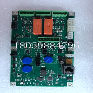
3HAC13389-2PLC工控备件
数据传输
其中两个USB端口位于前面板上,另两个则连接到后I/O。高速USB 2.0允许高达480 Mbyte/s的数据传输。此速率比USB 1.0快40倍。USB 2.0向后兼容USB 1.0。IDE接口:-7807上的IDE接口支持ATA-33、ATA-66和ATA-100驱动器,并根据使用的驱动器类型自动确定正确的操作模式。为了在ATA-100模式下正常工作,必须使用特殊的80导线电缆代替标准的40导线电缆。此电缆通常可从ATA-100驱动器制造商处获得。热管理:-7807采用了一个被动散热器,该散热器依赖于设备机架内以指定流速进行强制空气冷却。有关更多信息,请参阅环境规范。VMEbus接口:-7807 接口基于Newbridge/Tendra的Universe II高性能PCI到VMEbus接口。GE Fanuc Automation,股份有限公司.12090 South Memorial Parkway,Huntsville,Alabama 35803-3308 3-7807系统控制器:VMEbus系统控制器功能允许板作为插槽1控制器运行,或者在另一个板作为系统控制器时禁用。系统控制器可编程为提供以下仲裁模式:轮询(RRS)单级(SGL)优先级(PRI)系统控制器提供SYSCLK驱动程序、IACK*菊花链驱动程序和VMEbus访问超时计时器。如果在发出BGOUT*信号之后的指定时间段内没有看到BBSY*,则系统控制器还提供仲裁超时。该周期可编程为16或256µs。
VMEbus请求器:
微处理器可以在软件控制下使用任何VMEbus请求线(BR3*至BR0*)请求并控制总线。请求者可以编程为以以下任一模式运行:请求时释放(ROR)完成时释放(RWD)VMEbus捕获和保持(VCAP)邮箱:VMEbus接口提供四个32位邮箱,可从微处理器和访问,提供处理器间通信。当VMEbus访问邮箱时,邮箱能够中断微处理器。中断处理程序:中断处理程序监视并可编程以响应任何或所有VMEbus IRQ*线。所有正常进程VMEbus相关中断都可以映射到PCI INTA#或SERR#中断。其中包括:邮箱中断VMEbus中断VMEbus中断IACK周期(确认-7807 发出的中断)所有错误处理VMEbus的相关中断都可以映射到PCI INTA#或SERR#。注:PCI SERR#启动SBC NMI。其中包括:ACFAIL*中断BERR*中断SYSFAIL*interrupt中断处理器为每个IRQ*中断都有一个相应的STATUS/ID寄存器。一旦处理程序接收到IRQ*,它就请求VMEbus,一旦被授权,它就执行该级别的IACK循环。一旦IACK循环完成且STATUS/ID存储在相应的ID寄存器中,则在内部状态寄存器中设置适当的中断状态位,并生成PCI中断。PCI中断可以映射到PCI INTA#或SERR#。中断器:中断可以在软件控制下在七条VME总线中断线(IRQ7*至IRQ1*)中的任何一条或全部上发出。公共ID寄存器与所有中断线相关联。在中断确认周期期间,中断器向中断处理器发出ID。
data transmission
Two USB ports are located on the front panel and the other two are connected to the rear I/O. High speed USB 2.0 allows data transfer up to 480 Mbytes/s. This speed is 40 times faster than USB 1.0. USB 2.0 is backward compatible with USB 1.0. IDE interface: The IDE interface on the - 7807 supports ATA-33, ATA-66, and ATA-100 drives, and automatically determines the correct operation mode according to the drive type used. In order to work properly in ATA-100 mode, a special 80 conductor cable must be used instead of the standard 40 conductor cable. This cable is usually available from the ATA-100 drive manufacturer. Thermal management: - 7807 uses a passive radiator, which relies on the equipment rack for forced air cooling at a specified flow rate. For more information, see Environmental Specifications. VMEbus interface: - 7807 interface is based on Newbridge/Tendra's Universe II high-performance PCI to VMEbus interface. GE Fanuc Automation, Inc 12090 South Memorial Parkway, Huntsville, Alabama 35803-3308 3-7807 System Controller: The VMEbus system controller function allows the board to operate as a controller in slot 1, or it is disabled when another board is a system controller. The system controller can be programmed to provide the following arbitration modes: Round Robin (RRS) Single Level (SGL) Priority (PRI) The system controller provides the SYSCLK driver, IACK * daisy chain driver, and VMEbus access timeout timer. If BBSY * is not seen within the specified time period after BGOUT * signal is sent, the system controller also provides arbitration timeout. This cycle can be programmed to 16 or 256 µ s.
VMEbus requester:
The microprocessor can use any VMEbus request line (BR3 * to BR0 *) to request and control the bus under software control. The requester can be programmed to run in any of the following modes: Release on request (ROR) Release on completion (RWD) VMEbus capture and hold (VCAP) mailboxes: The VMEbus interface provides four 32-bit mailboxes, which can be accessed from the microprocessor and provide inter processor communication. When VMEbus accesses the mailbox, the mailbox can interrupt the microprocessor. Interrupt handler: The interrupt handler monitors and is programmable to respond to any or all VMEbus IRQ * lines. All VMEbus related interrupts of the normal process can be mapped to PCI INTA # or SERR # interrupts. These include: mailbox interrupt VMEbus interrupt VMEbus interrupt IACK cycle (confirm the interrupt sent by - 7807) All error handling VMEbus related interrupts can be mapped to PCI INTA # or SERR #. Note: PCI SERR # starts SBC NMI. These include: ACFAIL * Interrupt BERR * Interrupt SYSFAIL * interrupt The interrupt processor has a corresponding STATUS/ID register for each IRQ * interrupt. Once the handler receives IRQ *, it requests VMEbus, and once authorized, it executes the IACK loop at that level. Once the IACK cycle is completed and the STATUS/ID is stored in the corresponding ID register, set the appropriate interrupt status bit in the internal status register and generate a PCI interrupt. PCI interrupts can be mapped to PCI INTA # or SERR #. Interrupter: Interrupt can be sent on any or all of the seven VME buses (IRQ7 * to IRQ1 *) under software control. The common ID register is associated with all interrupt lines. During the interrupt acknowledgement cycle, the interrupter issues an ID to the interrupt processor.


