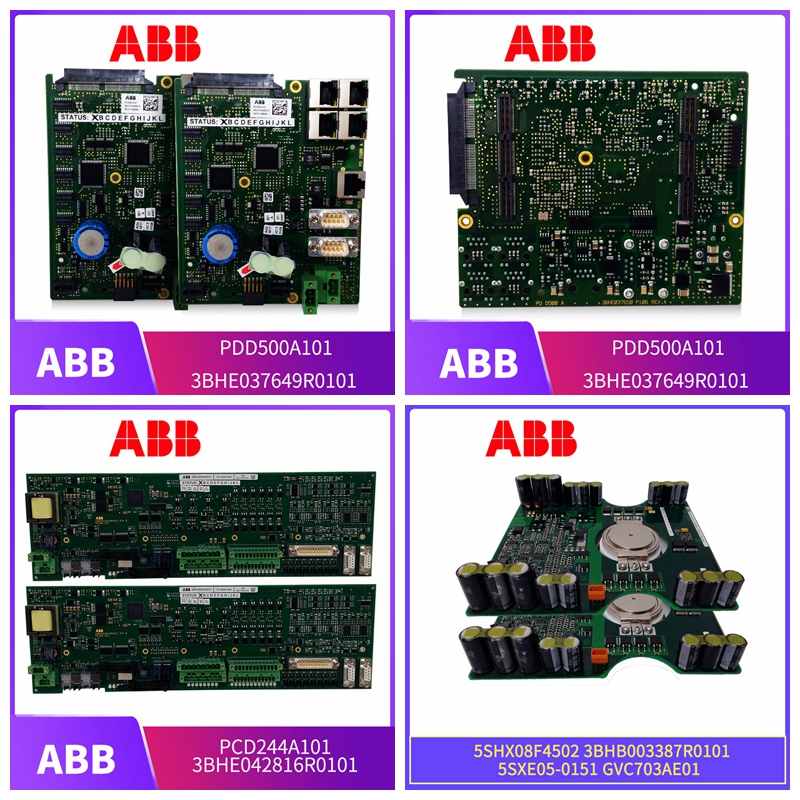
3BSC840157R1 PLC/DCS模块卡件
操作必须符合以下两个条件:
(1)本设备可能不会造成有害干扰,以及(2)本设备必须接受接收到的任何干扰,包括可能导致不期望操作的干扰。FCC A类注:根据FCC规则第15部分,该设备已测试并符合A类数字设备的限制。当设备在商业环境中运行时,这些限制旨在提供合理的保护,防止有害干扰。本设备产生、使用和辐射射频能量,如果未按照说明手册安装和使用,可能会对无线电通信造成有害干扰。在住宅区操作该设备可能会造成有害干扰,在这种情况下,用户需要自费纠正干扰。注意:未经负责合规的一方明确批准的更改或修改可能会使用户无权操作设备。加拿大法规VMIVME-7807/VME-7807RC A级数字设备符合加拿大ICES-003。注:任何测试和发现的符合FCC第15部分无意散热器或EN55022(以前的CISPR 22)要求的设备均符合ICES-003.66 VMIVME-8807/VME-7807RC产品手册本页为PC版,这确保了与各种系统的最大兼容性。本附录中的连接器图通常以自然方向显示,SBC安装在VME机箱中。A 68 A VMIVME-7807/VME-7807RC产品手册A1 D1 A32 D32 Z32 Z1 VME连接器引脚图A-1显示了VME P1和P2连接器及其原始M 1串行端口连接器RJ45引脚DIR RS232信号功能1输入DCD数据载体检测2输出RTS请求发送3 CGND机箱接地4输出TXD发送数据5输入RXD接收数据6接地7输入CTS清除发送8输出DTR数据的位置Terminal Ready 71鼠标/键盘连接器和引脚(J10)鼠标/键盘接头和引脚(J20)鼠标和键盘连接器(J10,J10)是一个标准的6针微型DIN PS/2连接器,如图A-4所示。
鼠标/键盘接口使用“Y”形分束器
电缆来分离鼠标和键盘信号。“Y”分路器电缆如第72页图A-5所示,插脚如第72页面表A-3所示。图A-4鼠标连接器和引脚1 2 3 4 5 6 J10键盘/鼠标连接器*引脚方向功能1输入/输出鼠标数据2输入/输出键盘数据3接地4+5V 5输出鼠标时钟6输出键盘时钟屏蔽机箱接地*VMIVME-7807/VME-7807RC随附适配器电缆,用于分离键盘和鼠标连接器。72 A VMIVME-7807/VME-7807RC产品手册图A-5鼠标/键盘Y分路器电缆注意:上面所示的鼠标/键盘引脚在鼠标电缆上有引脚2(键盘数据)和引脚6(键盘时钟)信号。这可能不适用于某些键盘和鼠标设备。我们建议您联系support.embeddedsystems@gefanuc.com了解更多信息。表A-3键盘/鼠标Y分路器电缆键盘鼠标引脚方向功能引脚方向功能1输入/输出键盘数据1输入/输入鼠标数据2未使用2未使用3接地3接地4+5V 4+5V 5输出键盘时钟5输出鼠标时钟6未使用6未使用屏蔽机箱接地屏蔽机箱接地线鼠标/键盘端口连接器(外螺纹)键盘连接器(内螺纹)鼠标连接器(内)引脚6引脚6引脚5引脚5引脚6引脚5键盘引脚2引脚1引脚1引脚2引脚2引脚3引脚4引脚4引脚3引脚3引脚73以太网连接器引脚输出(10/100Mbit)J15 A以太网连接器引脚输入(10/100M bit)J25以太网连接器J15的引脚输出图如图A-6所示。图A-6以太网连接器和引脚以太网连接器PIN信号名称1 TD+传输数据2 TD-传输数据3 GND接地4 CGND机箱GND 5 CGND底盘GND 6 GND接地线7 RX+接收数据8 RX-接收数据连接器开口引脚#1顶视图74 A VMIVME-7807/VME-7807RC产品手册PMC站点连接器和引脚PMC(J11)连接器和引脚图A-7 PMC(J21)连接器表A-4PMC(J11)接头引脚输出PMC接头(J11
The operation must meet the following two conditions:
(1) This equipment may not cause harmful interference, and (2) this equipment must accept any interference received, including interference that may cause undesired operation. FCC Class A Note: According to Part 15 of the FCC Rules, this equipment has been tested and meets the limits of Class A digital equipment. These limits are intended to provide reasonable protection against harmful interference when the equipment is operating in a commercial environment. This equipment generates, uses and radiates radio frequency energy. If it is not installed and used according to the instruction manual, it may cause harmful interference to radio communication. Operating the equipment in residential areas may cause harmful interference, in which case the user needs to correct the interference at his own expense. Note: Changes or modifications not expressly approved by the party responsible for compliance may result in users having no right to operate the equipment. Canadian regulation VMIVME-7807/VME-7807RC Class A digital equipment complies with Canadian ICES-003. Note: Any equipment tested and found to comply with the requirements of FCC Part 15 Unintentional Radiator or EN55,022 (formerly CISPR 22) complies with ICES-003.66 VMIVME-8807/VME-7807RC Product Manual This page is a PC version, which ensures maximum compatibility with various systems. The connector diagram in this appendix is usually displayed in the natural direction, and SBC is installed in VME chassis. A 68 A VMIVME-7807/VME-7807RC Product Manual A1 D1 A32 D32 Z32 Z1 VME connector pin diagram A-1 shows the VME P1 and P2 connectors and their original M 1 serial port connector RJ45 pin DIR RS232 signal function 1 input DCD data carrier detection 2 output RTS request sending 3 CGND chassis grounding 4 output TXD sending data 5 input RXD receiving data 6 grounding 7 input CTS clearing sending 8 output DTR data location Terminal Ready 71 mouse/keyboard connector and pin The (J10) mouse/keyboard connector and pin (J20) mouse and keyboard connector (J10, J10) is a standard 6-pin mini DIN PS/2 connector, as shown in Figure A-4.
The mouse/keyboard interface uses a "Y" beam splitter
Cable to separate mouse and keyboard signals. The "Y" splitter cable is shown in Figure A-5 on page 72 and the pins are shown in Table A-3 on page 72. Figure A-4 Mouse connector and pin 1 2 3 4 5 6 J10 keyboard/mouse connector * pin orientation function 1 I/O mouse data 2 I/O keyboard data 3 grounding 4+5V 5 output mouse clock 6 output keyboard clock shield chassis grounding * VMIVME-7807/VME-7807RC comes with adapter cable to separate keyboard and mouse connectors. 72 A VMIVME-7807/VME-7807RC Product Manual Figure A-5 Mouse/Keyboard Y Splitter Cable Note: The mouse/keyboard pin shown above has pin 2 (keyboard data) and pin 6 (keyboard clock) signals on the mouse cable. This may not apply to some keyboard and mouse devices. We suggest you contact support.embeddedsystems@gefanuc.com Learn more. Table A-3 Keyboard/Mouse Y Splitter Cable Keyboard Mouse Pin Direction Function Pin Direction Function 1 Input/Output Keyboard Data 1 Input/Input Mouse Data 2 Not Used 2 Not Used 3 Grounding 3 Grounding 4+5V 4+5V 5 Output Keyboard Clock 5 Output Mouse Clock 6 Not Used 6 Not Used Shielded Chassis Grounding Shielded Chassis Grounding Wire Mouse/Keyboard Port Connector (External Thread) Keyboard Connector (Internal Thread) Mouse Connector (Internal Thread) Pin 6 pin 6 pin 5 pin 6 pin 5 keyboard pin 2 pin 1 pin 2 pin 2 pin 3 pin 4 pin 3 pin 3 pin 73 Ethernet connector pin output (10/100Mbit) J15 A Ethernet connector pin input (10/100Mbit) J25 Ethernet connector J15 pin output diagram is shown in Figure A-6. Figure A-6 Ethernet connector and pin Ethernet connector PIN signal name 1 TD+transmit data 2 TD - transmit data 3 GND grounding 4 CGND chassis GND 5 CGND chassis GND 6 GND grounding wire 7 RX+receive data 8 RX receive data connector opening pin # 1 top view 74 A VMIVME-7807/VME-7807RC product manual PMC site connector and pin PMC (J11) connector and pin figure A-7 PMC (J21) connector table A-4 PMC (J11) connector pin output PMC connector (J11


