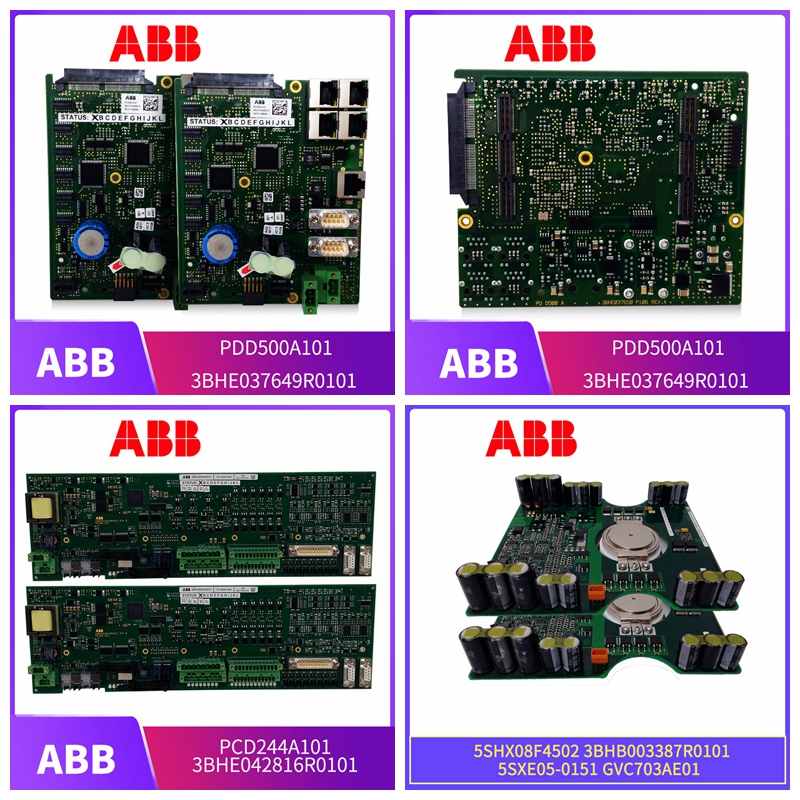
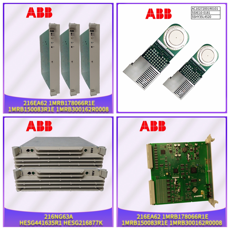
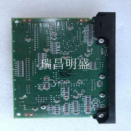
ABB 用于过程控制主板 PP5302B 3ADT306400R0001 PP5302
RV装置配置测量范围的上限值
DC诊断覆盖率运行时循环诊断功能覆盖的危险故障的分数。多点多点模式在多点模式下,最多15个现场设备并联连接到一对单线。模拟电流信号仅用于为双线技术中的设备供电,固定电流为≤ 4 mA。从一列更改为两列ProcessMaster FEP300、FEP500卫生Master FEH300、FEH500 | SM/FEX300/FEX500/SIL-EN Rev.D 5 2术语标准和定义2.1标准IEC 61508(2010),第1部分和第2部分-电气/电子/可编程电子安全相关系统的英文功能安全(目标群体:设备制造商和供应商)。-德国Funktional Sicherheit sicherheitsbezogener elektrischer/elektronischer/programmierbarer elektronicher Systeme(Zielgruppe:Hersteller und Lieferanten von Geräten)。2.2危险故障有可能使安全相关系统处于危险状态或使系统不工作的故障。2.3安全相关系统安全相关系统执行实现或维持安全状态所需的安全功能,例如在工厂中。例如:压力表、逻辑单元(如报警信号单元)和阀门构成安全相关系统。2.4安全功能由安全相关系统执行的特定功能,其目标是在考虑到已定义的危险事件的情况下,实现或维持工厂的安全状态。示例:极限压力监测3其他适用文件和文件流量计必须提供以下文件。
详细信息
这些文件包括模拟输出的功能规格以及如何操作和配置设备的详细信息。文件名称文件类型CI/FEX300/FEX500调试说明OI/FEX300/FEX500操作说明对于防爆设计的设备,还必须遵守安全说明。文件名称文件类型SM/FEX300/FEX500安全说明6 SM/FEX400/FEX500/SIL-EN Rev.D | ProcessMaster FEP300、FEP500 HygiicMaster FEH300、,FEH500 4确定安全完整性等级(SIL基于由流量计、逻辑单元和执行机构组成的完整安全功能系统的平均按需失效概率(PFDAVG)。安全完整性等级(SIL)PFDAVG(低需求模式)4≥ 10-5 … < 10-4 3 ≥ 10-4 … < 10-3 2 ≥ 10-3 … < 10-2 1 ≥ 10-2…<10-1下表显示了根据硬件容错(HFT),B类系统的完整安全相关系统可实现的安全完整性等级(SIL)。例如,B类系统是具有复杂组件(如微处理器)的传感器(见IEC 61508第2部分)。硬件容错(HFT)0 1 2 SIL 1 SIL 3 SIL 4 SIL 2(低需求模式)SIL2(高需求模式/连续模式)NOTICE ProcessMaster和HygiicMaster流量计满足HFT=0,适用于上表所述的安全相关系统。在低需求模式下,安全相关系统的需求率不超过每年一次,且不超过定期测试频率的两倍。ProcessMaster FEP300、FEP500卫生Master FEH300、FEH500 | SM/FEX300/FEX500/SIL-EN修订版。
Upper limit of measuring range of RV device configuration
DC diagnostic coverage Score of dangerous faults covered by the cycle diagnostic function during operation. Multipoint multipoint mode In multipoint mode, up to 15 field devices are connected in parallel to a pair of single wires. The analog current signal is only used to power the equipment in the two-wire technology, and the fixed current is ≤ 4 mA. Changed from one column to two columns ProcessMaster FEP300, FEP500 Health Master FEH300, FEH500 | SM/FEX300/FEX500/SIL-EN Rev. D 5 2 Terminology standards and definitions 2.1 Standard IEC 61508 (2010), Part 1 and Part 2 - Functional safety of electrical/electronic/programmable electronic safety related systems in English (target group: equipment manufacturers and suppliers)- Funktional Sicherheit sicherheitsbezogener elektrischer/elektronischer/programmierbarer elektronicher Systeme (Zielgruppe: Hersteller und Lieferanten von Ger ä ten), Germany. 2.2 Dangerous fault may make the safety related system in a dangerous state or make the system not work. 2.3 Safety Related Systems Safety related systems perform the safety functions required to achieve or maintain a safe state, such as in a factory. For example, pressure gauge, logic unit (such as alarm signal unit) and valve constitute a safety related system. 2.4 Safety Functions Specific functions performed by safety related systems, whose objective is to achieve or maintain the safety status of the plant in consideration of defined hazardous events. Example: Limit pressure monitoring 3 Other applicable documents and documents The flowmeter must provide the following documents.
detailed information
These files include functional specifications for analog outputs and details on how to operate and configure the device. Document Name Document Type CI/FEX300/FEX500 Commissioning Instructions OI/FEX300/FEX500 Operating Instructions For explosion-proof design equipment, safety instructions must also be followed. Document Name Document Type SM/FEX300/FEX500 Safety Instructions 6 SM/FEX400/FEX500/SIL-EN Rev. D | ProcessMaster FEP300, FEP500 HygicMaster FEH300, FEH500 4 Determine the safety integrity level (SIL is based on the average on demand failure probability (PFDAVG) of the complete safety functional system composed of flowmeter, logic unit and actuator). Safety integrity level (SIL) PFDAVG (low demand mode) 4 ≥ 10-5...<10-4 3 ≥ 10-4...<10-3 2 ≥ 10-3...<10-2 1 ≥ 10-2...<10-1 The following table shows the safety integrity level (SIL) that can be achieved by the complete safety related system of Class B system according to hardware fault tolerance (HFT). For example, Class B systems are sensors with complex components such as microprocessors (see IEC 61508 Part 2). Hardware fault tolerance (HFT) 0 1 2 SIL 1 SIL 3 SIL 4 SIL 2 (low demand mode) SIL 2 (high demand mode/continuous mode) NOTICE ProcessMaster and HygiicMaster flow meters meet HFT=0 and are applicable to the safety related systems described in the above table. In the low demand mode, the demand rate of safety related systems shall not exceed once a year, and shall not exceed twice the frequency of regular testing. ProcessMaster FEP300, FEP500 Health Master FEH300, FEH500 | SM/FEX300/FEX500/SIL-EN Revision.


