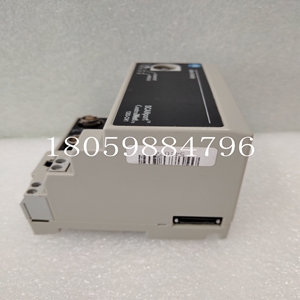
1203-CN1模块卡件
es特定设备的配置元素
当建立总线仲裁程序时,COMV被放置在传输时隙中,从最短周期的时隙开始。生成操作的结果可以打印出来。详细的打印输出包括:项目标识修订代码TEST_P指令周期总线仲裁器宏周期的持续时间(毫秒)宏周期中非周期性消息的百分比宏周期中的非周期性变量传输的百分比总线仲裁器的描述每个传输时隙的填充率设备交换描述应用变量和TVA之间的链接每个设备的网络接口构建报告每个I/O机架的处理接口构建报告3-26系列90-70 FIP总线控制器用户手册–1997年11月GFK-1038A配置PLC硬件硬件配置包括为所有数据分配映射写入Series 90-70 PLC参考区域中的选定存储区域。它还包括指定如何扫描数据(数据可以在不同的CPU扫描集中)。要编辑硬件配置:1.在网络配置工具窗口的左窗格中选择Series 90-70 PLC设备图标。2.在“工具”菜单上,单击“编辑硬件配置”。这将启动CIMPLICITY Control 90软件。从网络配置工具输入的设备将已就位。基本配置步骤1.配置CPU扫描模式。2.配置扫描集。3.配置FIP总线控制器。4.配置网络上的设备,如I/O机架、PLC和通用设备。3 GFK-1038A第3章配置3-27 CPU配置从Control 90机架显示器中选择PLC CPU以编辑CPU的硬件配置。现在可以使用以下选项卡:设置扫描内存故障扫描设置功耗除了应用程序所需的其他CPU配置之外,还可以为FIP系统进行以下选择。(此处不描述其他CPU配置步骤)。扫描在“扫描”选项卡上,选择扫描模式。–对于同步操作,请选择微循环。
为了实现最佳操作
微周期周期应与最快的同步扫描集相同(如“扫描集”选项卡所示)。–对于异步操作,可以选择任何模式。扫描集选择扫描集选项卡。最多可分配32个扫描集。其中,多达15个可以是同步的。配置扫描集的指南1.为非微循环模式(正常、恒定扫描、恒定窗口)配置的CPU只能为异步扫描集配置。分配给I/O的默认扫描集是固定扫描集(#1)。2.配置为微循环模式的CPU可以配置为同时具有异步和同步扫描集。3.同步扫描集可分配给本地机架I/O和非可触发FBC的FIP总线控制器。这允许同步扫描集包括异步I/O。4.在触发FIP总线控制器中,分配给一个同步扫描集的所有TVA和COMV可以具有不同的时隙。然而,时隙必须共享同一时段。输出延迟为0,无法更改。5.如果同步扫描集已配置但尚未分配给FIP总线控制器的时隙(因此其周期为0),则整个配置无效。扫描集配置步骤A。要配置异步扫描集:1.输入扫描集的描述。2.选择“异步”作为扫描集类型。3.无法编辑“事件源”和“单一名称”的条目。3 3-28系列90-70 FIP总线控制器用户手册–1997年11月GFK-1038A 4.选择扫描次数作为扫描集的频率。5.选择输出延迟,指示发送输出前要延迟的扫描次数。B、 要配置同步扫描集:1.输入扫描集的描述。2.选择“同步”作为扫描集的类型。(要配置同步扫描集,必须在网络配置工具中将PLC的网络访问参数设置为“/时隙”(同步)。3.以rack.slot格式输入事件源,以识别触发FIP总线控制器。例如,如果机架0插槽2中的FIP总线控制器是触发FIP总线的控制器,则输入0.2.4。单一名称将由编程器分配,并用于指定任务定义中的“单一”字段以触发应用程序。5.#扫描/周期是同步扫描集的不可编辑字段。当在FIP总线控制器扫描选项卡中将时隙分配给该扫描集时,将在此显示该扫描集的周期。扫描集配置参数参数范围或选项注释#(扫描集的)1–32扫描集1是固定的,不可编辑;其类型为异步,扫描次数为1,输出延迟为0。描述最多32个字符类型同步,异步在异步扫描模式下,数据作为扫描周期的一部分读取。在同步模式下,当FIP总线控制器触发时读取数据。如果类型为同步,则必须指定事件源(请参见下文)。如果类型为异步,请指定扫描次数和输出延迟。事件源如果类型为SYNC,这是与扫描集同步的FIP总线控制器的机架/插槽地址。例如,机架0插槽4为0.4。单一名称如果类型为SYNC,将自动提供单一名称。扫描次数或周期(mS)0–1024mS如果类型为SYNC
The configuration elements of the es specific device
When establishing the bus arbitration program, COMV is placed in the transmission slot, starting from the slot with the shortest cycle. The result of the generation operation can be printed. Detailed printout includes: Item ID revision code TEST_ Duration of the P instruction cycle bus arbiter macro cycle (milliseconds) Percentage of aperiodic messages in the macro cycle Percentage of aperiodic variable transmission in the macro cycle Bus arbiter Description of the fill rate of each transmission timeslot Device exchange Description of the link between application variables and TVA Network interface construction report of each device Processing interface construction report of each I/O rack 3-26 series 90-70 FIP bus controller User's Manual – November 1997 GFK-1038A configuration PLC hardware hardware configuration includes all data The allocation map is written to the selected storage area in the Series 90-70 PLC reference area. It also includes specifying how to scan data (data can be in different CPU scan sets). To edit the hardware configuration: 1. Select the Series 90-70 PLC device icon in the left pane of the Network Configuration tool window. 2. On the Tools menu, click Edit Hardware Configuration. This will launch the CIMPLICITY Control 90 software. The device entered from the network configuration tool will be in place. Basic configuration step 1. Configure the CPU scanning mode. 2. Configure the scan set. 3. Configure FIP bus controller. 4. Configure the equipment on the network, such as I/O rack, PLC and general equipment. 3 GFK-1038A Chapter 3 Configuration 3-27 CPU Configuration Select the PLC CPU from the Control 90 rack display to edit the CPU hardware configuration. You can now use the following tabs: Set Scan Memory Failure Scan Set Power Consumption In addition to other CPU configurations required by the application, you can also make the following selections for FIP systems. (Other CPU configuration steps are not described here.). Scan On the Scan tab, select the scan mode. – For synchronous operations, select Microcycle.
For best practices
The microcycle period should be the same as the fastest synchronous scan set (as shown in the Scan Set tab). – For asynchronous operations, you can select any mode. Scan Sets Select the Scan Sets tab. A maximum of 32 scan sets can be allocated. Up to 15 of them can be synchronized. Guidelines for configuring scan sets 1. CPU configured for non microcirculation mode (normal, constant scan, constant window) can only be configured for asynchronous scan sets. The default scan set assigned to I/O is the fixed scan set (# 1). 2. CPUs configured in microcirculation mode can be configured with both asynchronous and synchronous scan sets. 3. Synchronous scan sets can be assigned to local rack I/O and FIP bus controllers of non trigger FBCs. This allows synchronous scan sets to include asynchronous I/O. 4. In the trigger FIP bus controller, all TVAs and COMVs assigned to a synchronous scan set can have different time slots. However, time slots must share the same time period. The output delay is 0 and cannot be changed. 5. If the synchronization scan set has been configured but has not been allocated to the time slot of the FIP Bus Controller (so its cycle is 0), the entire configuration is invalid. Scan set configuration step A. To configure an asynchronous scan set: 1. Enter a description of the scan set. 2. Select Asynchronous as the scan set type. 3. The entries for Event Source and Single Name cannot be edited. 3 3-28 Series 90-70 FIP Bus Controller User's Manual – November 1997 GFK-1038A 4. Select the number of scans as the frequency of the scan set. 5. Select Output Delay to indicate the number of scans to be delayed before sending the output. B. To configure a synchronous scan set: 1. Enter a description of the scan set. 2. Select Synchronize as the scan set type. (To configure a synchronous scan set, the network access parameter of the PLC must be set to "/time slot" (synchronization) in the network configuration tool. 3. Use rack Enter the event source in slot format to identify the trigger FIP bus controller. For example, if the FIP bus controller in rack 0 slot 2 is the controller that triggers the FIP bus, enter 0.2.4. A single name is assigned by the programmer and is used to specify a "single" field in the task definition to trigger the application. 5. # Scan/Period is a non editable field of synchronous scan set. When timeslots are assigned to the scan set in the FIP Bus Controller Scan tab, the cycle of the scan set is displayed here. Scan Set Configuration Parameter Range or Option Note # (of scan set) 1 – 32 Scan Set 1 is fixed and cannot be edited; Its type is asynchronous, the number of scans is 1, and the output delay is 0. Describes the synchronization of up to 32 character types. In asynchronous scanning mode, data is read as part of the scanning cycle. In synchronous mode, data is read when the FIP Bus Controller triggers. If the type is synchronous, you must specify an event source (see below). If the type is asynchronous, specify the number of scans and output delay. If the event source is SYNC, this is the rack/slot address of the FIP Bus Controller synchronized with the scan set. For example, rack 0 slot 4 is 0.4. Single Name If the type is SYNC, a single name is automatically provided. Number of scans or cycles (mS) 0 – 1024mS if the type is SYNC


