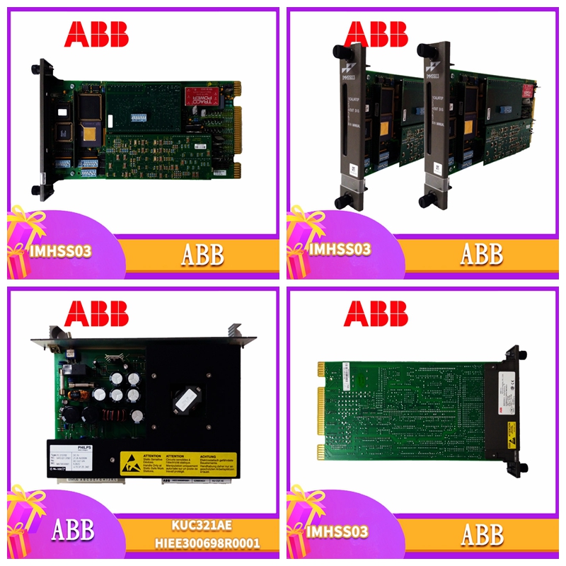
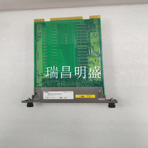
DSPB120 57340001-T 工控模块卡件
串行总线接线端子1至4用于串行总线。如果模块将用作BSM控制器,首先在模块的串行总线端子上安装总线交换模块。然后将串行总线电缆连接到BSM端子,如总线交换模块数据表所述。将BSM的任何一根尾光纤连接到端子10。将第二根BSM导线连接到N端子。使用《系统和通信用户手册》中推荐的电缆类型之一,将串行总线连接到端子1-4.1 2 3 4串行1串行2屏蔽输入屏蔽输出如果块位于总线的任一端,则在其串行1和串行2端子两端连接适当类型的端接电阻器(详见《系统和通讯用户手册》)。串行1串行2屏蔽输入屏蔽输出总线终端电阻器串行1串行1屏蔽输入屏蔽输入输出终端电阻器如果您想在不断开输入设备电源的情况下禁用块,请使用块拔出器拔出电子组件。请勿断开H或N以断开电源。现场接线将I/O设备的接线连接到端子10-17。将双线输出设备连接到N,将双线输入设备连接到H,如下图所示。如右图所示,连接三线设备。注:端子5-9和18-22连接在端子组件N AC电源 输出信号(热未使用)典型输出设备接线(10-17)N中性输入信号(中性未使用)标准输入设备接线(10-17)H H 5~N H设备1 N H设备2 N H设备3 N H设备4 N H设备5 N H设备6N H设备7 N H设备8将115伏交流电源连接到接线板上的一个H端子上。将空档连接到N端子。所有H端子和所有N端子均采用内部总线连接。额外的电源端子是为了方便。根据物理布局和当前负载,热连接可以通过总线连接在一起,并通过一根导线连接到块或电源。
中性点连接也可以用母线连接在一起,并由一根导线连接。任何电路都可以是输入或输出。通过输入设备(如开关)将电源连接到块上的离散输入电路。对于输出,功率通过模块电子线路传输到离散电路并施加到负载。将负载回路连接到N端子。将模块上的所有电源连接至相同的120 VAC相位。不同的块之间可以有不同的相位。块1输出设备输入设备115 VAC PHASE 1 N H N块2输出设备输入装置115 VAC PHASE 2 N H N Power Disconnects由于块电源与电路电源相同,因此重要的是要将块电源与输入电源同时断开。负载AC块N是否H电源断开~警告:如果I/O电路电源未与块电源同时断开,即使块上的一条电源线已断开,当激活多个输入时,块可能会通电。三态输入接线如果输入电路报告开路情况,则在输入设备的干触点上安装一个5.1K欧姆、1/2瓦或更大的无感电阻器。电路必须配置为三态输入。IN H N ~外部抑制如果接线盒和负载之间有触点,则在负载上安装抑制装置。电阻电容抑制器是低电流、高电感负载的首选。对于高功率负载,请使用电压钳位装置,如MOV。还建议使用RC抑制器来减少电磁干扰。如果要在设备通电的情况下切换电源,电源侧开关可能需要线对线抑制。有关使用抑制的更多信息,请参阅离散和模拟块用户手册。
Serial bus terminals 1 to 4 are used for the serial bus. If the module will be used as a BSM controller, first install the bus switching module on the serial bus terminal of the module. Then connect the serial bus cable to the BSM terminals as described in the Bus Switching Module Data Sheet. Connect any pigtail of the BSM to terminal 10. Connect the second BSM wire to the N terminal. Use one of the cable types recommended in the System and Communication User's Manual to connect the serial bus to terminals 1-4.1 2 3 4 Serial 1 Serial 2 Shielded Input Shielded Output If the block is located at either end of the bus, connect the appropriate type of termination resistors at both ends of its serial 1 and serial 2 terminals (see System and Communication User's Manual for details). Serial 1 Serial 2 Shielded Input Shielded Output Bus Terminator Serial 1 Serial 1 Shielded Input Shielded I/O Terminator If you want to disable the block without disconnecting power to the input device, use the block puller to unplug the electronics. Do not disconnect H or N to disconnect the power supply. Field wiring connects the wiring of the I/O device to terminals 10-17. Connect the two-wire output device to N and the two-wire input device to H, as shown in the following figure. Connect the three wire device as shown in the right figure. Note: Terminals 5-9 and 18-22 are connected to terminal assembly N AC power output signal (hot not used) Typical output device wiring (10-17) N Neutral input signal (neutral not used) Standard input device wiring (10-17) H H 5~N H device 1 N H device 2 N H device 3 N H device 4 N H device 5 N H device 6 N H device 7 N H device 8 Connect 115 V AC power to an H terminal on the terminal block. Connect neutral to terminal N. All H terminals and all N terminals are connected by internal bus. Additional power terminals are for convenience. Depending on the physical layout and the current load, hot connections can be connected together via a bus and connected to a block or power supply via a single wire.
The neutral connection can also be connected together by bus and connected by a conductor. Any circuit can be an input or an output. The power supply is connected to the discrete input circuit on the block by an input device, such as a switch. For the output, power is transmitted to the discrete circuit via the module electronic circuit and applied to the load. Connect the load loop to the N terminal. Connect all power supplies on the module to the same 120 VAC phase. Different blocks can have different phases. Block 1 Output Device Input Device 115 VAC PHASE 1 N H N Block 2 Output Device Input Device 115 VAC PHASE 2 N H N Power Disconnects Since the block power supply is the same as the circuit power supply, it is important to disconnect the block power supply and the input power supply at the same time. Whether the load AC block N is powered off~Warning: If the I/O circuit power supply is not disconnected from the block power supply at the same time, even if one of the power lines on the block is disconnected, the block may be powered on when multiple inputs are activated. Three state input wiring If the input circuit reports an open circuit, install a 5.1K ohm, 1/2 watt, or greater noninductive resistor on the dry contact of the input device. The circuit must be configured as a three state input. IN H N~External suppression If there is a contact between the junction box and the load, install a suppression device on the load. Resistance capacitance suppressor is the first choice for low current and high inductance load. For high power loads, use voltage clamping devices such as MOVs. It is also recommended to use RC suppressors to reduce electromagnetic interference. If you want to switch the power supply when the equipment is powered on, the power side switch may require line to line suppression. For more information on using suppression, see the Discrete and Analog Block User's Manual.


