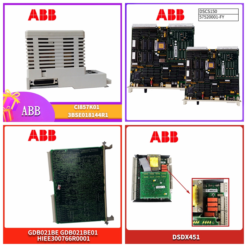
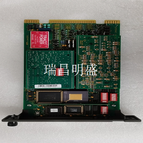
DSMB175 57360001-KG PLC工控模块
电源断开
由于块电源与电路电源相同,因此必须将块电源断开,以便块电源和输入电源同时断开。负载AC块N是否H~警告:如果I/O电路电源未与块电源同时断开,则当激活多个输入时,块可能会通电,即使从块上断开了一条电源线。如果您想在不切断输入设备电源的情况下禁用块,请使用块拔出器拔出电子组件。请勿断开H或N以断开电源。短路检测接线如果电路将使用可配置的短路检测功能,则可能需要安装与输入设备串联的电阻器。对于默认阈值和干接触传感器,使用3.9K欧姆电阻器。如果阈值发生变化,则必须按照《离散和模拟块用户手册》中的说明选择电阻值。对于某些固态传感器,可能不需要额外的外部电阻。请参考传感器制造商的规格。N H Rs IN ~开路检测布线如果电路将使用可配置的开路检测功能,则可能需要在输入设备的端子之间安装电阻器。对于干接触传感器,默认阈值不变,可使用22K欧姆电阻器。如果阈值发生变化,则必须按照《离散和模拟块用户手册》中的说明选择电阻器。对于某些固态传感器,可能不需要额外的外部电阻。请参考传感器制造商的规格。N H IN Rp~可为同一输入选择开路和短路诊断。然后,输入电路必须包括串联电阻器和并联电阻器,以检测干接触传感器的开路/短路情况。如果将使用块的默认阈值,请使用上面给出的电阻值。
端子组件固定螺钉
N H IN Rp Rs~拆卸电子组件_块的电子组件可更换为兼容型号,无需拆卸现场接线或重新配置块。端子组件固定螺钉(数量2)电子组件连接器引脚1.拧下块顶部和底部的固定螺钉。2.使用块拉拔器(IC660BLM507),将凸耳接合在第一个通风槽中。将工具移动到块的中心并挤压手柄。3.向上拉动电子组件。警告:如果现场端子通电,端子组件底部的连接器引脚也会暴露电源,存在触电危险。请勿接触接头针脚!可能导致死亡或受伤。插入电子组件1.将电子组件对准导轨并用力向下推。注意不要用力过猛;它可能会损坏块。2.如果遇到异常电阻,拆下电子组件。如果模块通电,请勿触摸连接器插脚!检查端子组件、连接器插座和连接器边缘板(在电子组件上)。确保键匹配。清除所有障碍物并重新插入电子组件。密切注意导销的对准。3.用端子顶部和底部的螺钉固定电子组件
Power off
Since the block power supply is the same as the circuit power supply, the block power supply must be disconnected so that the block power supply and the input power supply are disconnected at the same time. Whether the load AC block N is H~Warning: If the I/O circuit power supply is not disconnected from the block power supply at the same time, the block may be powered up when multiple inputs are activated, even if a power cord is disconnected from the block. If you want to disable the block without powering off the input device, use the block puller to unplug the electronics. Do not disconnect H or N to disconnect the power supply. Short circuit detection wiring If the circuit will use the configurable short circuit detection function, you may need to install a resistor in series with the input device. For default threshold and dry contact sensors, use a 3.9K ohm resistor. If the threshold value changes, the resistance value must be selected as described in the Discrete and Analog Block User's Manual. For some solid-state sensors, additional external resistance may not be required. Refer to the sensor manufacturer's specifications. N H Rs IN~Open circuit detection wiring If the circuit will use the configurable open circuit detection function, it may be necessary to install a resistor between the terminals of the input device. For dry contact sensors, the default threshold is unchanged and a 22K ohm resistor can be used. If the threshold value changes, the resistor must be selected as described in the Discrete and Analog Block User's Manual. For some solid-state sensors, additional external resistance may not be required. Refer to the sensor manufacturer's specifications. NHIN Rp~can select open circuit and short circuit diagnosis for the same input. The input circuit must then include a series resistor and a parallel resistor to detect open/short circuits in the dry contact sensor. If the default threshold of the block will be used, use the resistance value given above.
Terminal assembly fixing screw
N H IN Rp Rs~Remove electronic components_ The electronic components of the block can be replaced with compatible models without dismantling the field wiring or reconfiguring the block. Terminal assembly fixing screws (Qty. 2) Electronic assembly connector pin 1. Unscrew the fixing screws at the top and bottom of the block. 2. Use the block puller (IC660BLM507) to engage the lug in the first ventilation slot. Move the tool to the center of the block and squeeze the handle. 3. Pull the electronic assembly upwards. Warning: If the field terminal is powered on, the connector pin at the bottom of the terminal assembly will also expose the power supply, which may cause electric shock. Do not touch the connector pins! May cause death or injury. Insert the electronic assembly 1. Align the electronic assembly with the guide rail and push down firmly. Be careful not to exert too much force; It may damage the block. 2. If abnormal resistance is encountered, remove the electronic components. If the module is powered, do not touch the connector pins! Check the terminal assembly, connector socket and connector edge plate (on the electronic assembly). Make sure the keys match. Remove all obstacles and reinsert the electronic components. Pay close attention to the alignment of the guide pins. 3. Fix the electronic components with the screws at the top and bottom of the terminal


