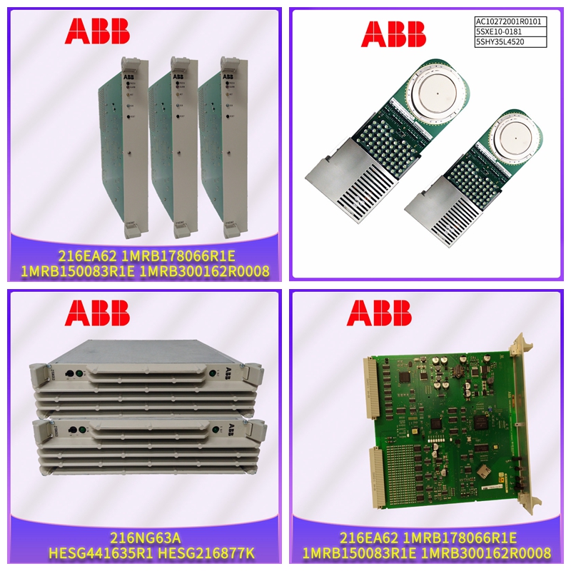
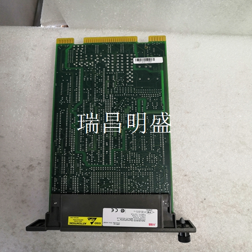
DSCS116 57520001-BZ 工控模块备件
安装在水平表面上
可选支架旨在便于安装在水平表面上。1.标记安装孔的位置。2.根据第D.15节,尺寸图,3BSE010457,A版,钻孔并切割螺纹。3.根据第D.8节,安装称重传感器中的说明进行安装。为了获得最佳的测量方向,在钻安装孔之前,将称重传感器转到合适的位置。使用支架安装的可能方法。支架张力电子设备PFEA111/112,用户手册附录D PFRL 101-设计称重传感器安装D-12 3BSE029380R0001 D.8.2称重传感器的安装螺钉应根据表D-1使用螺钉安装称重传感器。注:应根据制造商的建议拧紧螺钉。强度等级为8.8的螺钉足以在没有较大横向力或过载的情况下正常使用。在可能出现较大横向力或过载的应用中,建议使用强度等级为12.9且拧紧力矩更高的螺钉。安装前,检查安装表面是否清洁平整,如无毛刺和其他损坏。D、 8.3称重传感器电缆的布线电缆必须用夹子支撑并布线,以防止通过电缆的力分流。表D-1.安装螺钉称重传感器PFRL 101螺钉尺寸A M8(5/16 UNC)B M8(5/6 UNC)C M10(3/8 UNC)D M12(1/2 UNC)测量方向横向张力电子设备PFEA111/112,用户手册第D.9节技术数据3BSE029380R0001 D-13 D.9技术数据表D-2。不同类型称重传感器的技术数据PFRL 101 PFRL 101-类型数据单元标称负载标称低压电子设备PFEA111/112,用户手册附录D PFRL 100-设计称重传感器安装D-14 3BSE029380R0001材料A B C D SS 2387不锈钢,DIN X4CrNiMo 16 5。耐腐蚀性能与AISI 304相似。
精度精度等级
±0.5%重复性误差<±0.1补偿温度范围+20-+80(68-176)°C(°F)零点漂移150(83)ppm/K(ppm/F)灵敏度漂移150(8.3)工作温度范围-10-+80-(14-176)°F)零点漂移300(167)ppm/K(ppm/F)灵敏度漂移300(67)存储温度范围-40-+80。不同类型称重传感器PFRL 101 PFRL 01类型数据单元张力电子设备PFEA111/112的技术数据,用户手册第D.10节电缆图,3BSE028140D0065,第3/5页,B版3BSE039380R0001 D-15 D.10电缆图,第3BSE04140D0065页,第3/6页,B版本张力电子设备,用户手册附录D PFRL 101-设计称重传感器安装D-16 3BSE029380R0001 D.11电缆图,3BSE048140D0065,第4/5页,B版张力电子设备PFEA111/112,用户手册第D.12节尺寸图3BSE004042D0003,第1/2页,M版3BSE039380R001 D-17 D.12尺寸图3SSE004042D0003,用户手册附录D PFRL 101-设计称重传感器安装D-18 3BSE029380R0001 D.13尺寸图,3BSE004042D0003,第2/2页,版次M张力电子设备PFEA111/112,用户手册第D.14节尺寸图,第3BSE04042D0065,版次-3BSE0292380R0001 D-19 D.14尺寸图,用户手册附录D PFRL 101-设计称重传感器装置D-20 3BSE029380R0001 D.15尺寸图,3BSE010457,A版张力电子设备PFEA111/112,用户手册第E.1节关于本附录3BSE039380R001E-1附录E PFTL 101-称重传感器装置设计E.1关于本附录本附录描述了称重传感器装置的设计程序。包括以下章节:•基本应用注意事项•设计称重传感器安装(分步指南)•安装要求•力和缠绕增益计算–水平安装–倾斜安装–单侧测量•安装称重传感器•技术数据•图纸–电缆图–尺寸图–组装图纸E.2基本应用注意事项每个应用都有其需要考虑的单独要求;尽管一些基本考虑往往会重复。•涉及哪种类型的工艺(造纸、转化等)?环境是否苛刻(温度、化学品等)?•张力测量的目的是什么;指示还是闭环控制?是否有任何具体的精度要求?•机器的设计是什么样的?是否有可能修改设计,以便安装最合适的称重传感器,或者机器设计是否固定?•作用在辊上的力是什么样的(大小和方向)?它们可以通过重新设计来改变吗?如果彻底解决了这些问题,安装很有可能成功。然而,需要测量精度的程度定义了设计称重传感器时的要求
Installed on a horizontal surface
The optional bracket is designed for easy mounting on a horizontal surface. 1. Mark the position of mounting hole. 2. Drill and cut threads according to Section D.15, Dimensional Drawing, 3BSE010457, Rev. A. 3. According to Article D Section 8, Installing the Load Cell. In order to obtain the best measurement direction, turn the load cell to the proper position before drilling the installation hole. Possible methods of mounting with brackets. Support tension electronic equipment PFEA111/112, User Manual Appendix D PFRL 101 - Design Load Cell Installation D-12 3BSE029380R0001 D.8.2 The mounting screws of the load cell shall be used to install the load cell according to Table D-1. NOTE: Screws should be tightened according to the manufacturer's recommendations. The strength grade 8.8 screw is sufficient for normal use without large lateral force or overload. In applications where large lateral forces or overloads may occur, it is recommended to use screws with a strength class of 12.9 and a higher tightening torque. Before installation, check whether the installation surface is clean and flat, such as free of burrs and other damages. D. 8.3 The wiring cable of the load cell cable must be supported and routed with clips to prevent the force flow through the cable. Table D-1. Mounting screw Load cell PFRL 101 Screw size A M8 (5/16 UNC) B M8 (5/6 UNC) C M10 (3/8 UNC) D M12 (1/2 UNC) Measuring direction Transverse tension electronic device PFEA111/112, User's Manual, Section D Section 9 Technical Data 3BSE029380R0001 D-13 D.9 Technical Data Sheet D-2. Technical data of different types of load cells PFRL 101 PFRL 101 - Type data unit Nominal load Nominal low voltage electronic equipment PFEA111/112, User's Manual Appendix D PFRL 100 - Design load cell installation D-14 3BSE029380R0001 Material A B C D SS 2387 stainless steel, DIN X4CrNiMo 16 5. Corrosion resistance is similar to AISI 304.
Accuracy class
± 0.5% repeatability error<± 0.1 compensation temperature range+20 -+80 (68-176) ° C (° F) zero drift 150 (83) ppm/K (ppm/F) sensitivity drift 150 (8.3) operating temperature range - 10 -+80 - (14-176) ° F) zero drift 300 (167) ppm/K (ppm/F) sensitivity drift 300 (67) storage temperature range - 40 -+80. Different types of load cells PFRL 101 PFRL 01 type data unit Technical data of tension electronics PFEA111/112, User's Manual, Section D Section 10 Cable Drawing, 3BSE028140D0065, Page 3/5, Version B 3BSE039380R0001 D-15 D.10 Cable Drawing, Page 3BSE04140D0065, Page 3/6, Version B Tension Electronics, User Manual Appendix D PFRL 101 - Design Load Cell Installation D-16 3BSE029380R0001 D.11 Cable Drawing, 3BSE048140D0065, Page 4/5, Version B Tension Electronics PFEA111/112, User Manual Chapter D Section 12 Dimension Drawing 3BSE004042D0003, Page 1/2, Version M 3BSE039380R001 D-17 D.12 Dimension Drawing 3SSE004042D0003, User Manual Appendix D PFRL 101 - Design Load Cell Installation D-18 3BSE029380R0001 D.13 Dimension Drawing, 3BSE004042D0003, Page 2/2, Version M Tension Electronics PFEA111/112, User Manual Chapter D Section 14 Dimensional Drawings, 3BSE04042D0065, Rev. - 3BSE0292380R0001 D-19 D.14 Dimensional Drawings, User Manual Appendix D PFRL 101 - Design of Load Cell Devices D-20 3BSE029380R0001 D.15 Dimensional Drawings, 3BSE010457, Version A Tension Electronics PFEA111/112, User Manual Section E Section 1 About Appendix E PFTL 101 Load Cell Device Design E of this Appendix 3BSE039380R001E-1 1 About this appendix This appendix describes the design procedure of the load cell device. The following sections are included: • Basic application considerations • Design load cell installation (step-by-step guide) • Installation requirements • Force and winding gain calculation – Horizontal installation – Inclined installation – One side measurement • Installing load cells • Technical data • Drawings – Cable drawings – Dimensional drawings – Assembly drawings E 2 Basic application considerations Each application has its own requirements to consider; Although some basic considerations are often repeated. • What type of process is involved (papermaking, conversion, etc.)? Is the environment harsh (temperature, chemicals, etc.)? • What is the purpose of tension measurement; Indication or closed-loop control? Are there any specific accuracy requirements? • What is the design of the machine? Is it possible to modify the design to install the most suitable load cell, or is the machine design fixed? • What is the force acting on the roll (magnitude and direction)? Can they be changed by redesign? If these problems are completely solved, the installation is likely to succeed. However, the degree of measurement accuracy required defines the requirements for designing load cells


