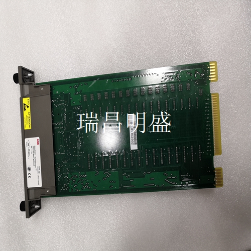
CI560 3UBRC980002R0001 工控备件模块卡件
安装说明
1称重传感器电缆的布线电缆必须用夹具支撑并布线,以防止力通过电缆分流。2连接称重传感器延伸电缆参见第B.10节,安装说明,电缆连接器,,A版。注!L T伸入测压元件。螺钉不得L<T Tension Electronics ,用户手册第B.8节技术数据B-9 B.8技术数据+-!测量方向上的标称载荷,Fnom 0.2(45)0.5(112)1.0(225)kN(lbs)精度范围内的允许横向载荷,FVnom对于h=135 mm(5.3英寸)0.05(11)0.125(28)0.25(56)精度范围的允许轴向载荷,FAnom对于h=135 mm)5.3英寸)0.05(11)0.25,Fext 0.3(67)0.75(169)1.5(337)0 1无数据永久变化的测量方向最大载荷,Fmax 1)0.6(135)1.5(33)3(674)kN无数据永久性变化的横向最大载荷(lbs),FVmax(1)。对于h=135 mm(5.3英寸)(1),允许同时使用Fmax和FVmax。0.3(67)0.75(169)1.5(337)“9(52)22(124)34(197)kN/mm(1000 lbs/in)1精度等级,压缩力±1.0%线性偏差<±0.5重复性误差<±0.1滞后<±0.3不带转接板的重量约2.5(约5.5)kg(lbs)包括转接板在内的重量约5.4(约11.9)长度、宽度和高度见第B.11节,尺寸图,3BSE015955D0094,B版。称重传感器SS 2387不锈钢,DIN X4CrNiMo 165。耐腐蚀性能与AISI 304相似。适配器板SS 1312,经黑色铬酸盐处理。ASTM A 238-79 C级。
安装螺钉5镀锌钢螺钉
用油或乳液润滑。强度等级符合ISO 898/1.8.8 M8 24 Nm(18 ft-lb)张力电子设备,用户手册第B.9节电缆图3BSE028140D0065,第2/5页,B版 B-11 B.9电缆图3SSE0281140D0065第2/5版,B版张力电子设备,用户手册附录B PFCL 301E-设计称重传感器安装B-12 3BSE049380R001 B.10安装说明,电缆连接器,,版本A张力电子设备,用户手册第B.11节尺寸图,3BSE115955D0094,版本B B-13 B.11尺寸图,,版本B张力电子设备,用户手册附录B PFCL 301E-设计称重传感器安装B-14 B.12装配图,。A Tension Electronics ,用户手册第C.1节关于本附录C-1附录C PFTL 301E-设计称重传感器装置C.1关于本附录本附录描述了称重传感器装置的设计程序。包括以下章节:•基本应用注意事项•设计称重传感器安装(分步指南)•安装要求•力和缠绕增益计算–水平安装–倾斜安装–单侧测量•安装称重传感器•技术数据•图纸–电缆图–称重传感器安装说明延长电缆-尺寸图-装配图
Installation Instructions
1 The wiring cable of the load cell cable must be supported and routed with clamps to prevent the force from being shunted through the cable. 2 Connect the load cell extension cable, see Section B Section 10, Installation Instructions, Cable Connectors, Version A. Note! L T extends into the load cell. The screw shall not be L<T Tension Electronics, Section B of the User's Manual Section 8 Technical Data B-9 B.8 Technical Data+-! The nominal load in the measurement direction, the allowable transverse load within the accuracy range of Fnom 0.2 (45) 0.5 (112) 1.0 (225) kN (lbs), the allowable axial load within the accuracy range of h=135 mm (5.3 in) 0.05 (11) 0.125 (28) 0.25 (56) for FVnom, the maximum load in the measurement direction without permanent change of data for FAnom h=135 mm (5.3 in) 0.05 (11) 0.25, Fext 0.3 (67) 0.75 (169) 1.5 (337) 0 1, Fmax 1) 0.6 (135) 1.5 (33) 3 (674) kN maximum transverse load (lbs) without permanent change of data, FVmax (1). For h=135 mm (5.3 inches) (1), both Fmax and FVmax are allowed. 0.3 (67) 0.75 (169) 1.5 (337) "9 (52) 22 (124) 34 (197) kN/mm (1000 lbs/in) 1 accuracy grade, compression force ± 1.0% linear deviation<± 0.5 repeatability error<± 0.1 hysteresis<± 0.3 weight without adapter plate approx. 2.5 (approx. 5.5) kg (lbs) weight including adapter plate approx. 5.4 (approx. 11.9) For length, width and height, see Section B Section 11, Dimensional Drawing, 3BSE015955D0094, Rev. B. Load cell SS 2387 stainless steel, DIN X4CrNiMo 165. Corrosion resistance is similar to AISI 304. Adapter plate SS 1312, black chromated. ASTM A 238-79 Grade C.
Mounting screw 5 Galvanized steel screw
Lubricate with oil or lotion. Strength grade according to ISO 898/1.8.8 M8 24 Nm (18 ft lb) tension electronics, user manual, section B Section 9 Cable Drawing 3BSE028,140D0065, Page 2/5, Version B B-11 B.9 Cable Drawing 3SSE0,281,140D0065, Version 2/5, Version B Tension Electronics, User Manual Appendix B PFCL 301E - Design Load Cell Installation B-12 3BSE049,380R001 B.10 Installation Instructions, Cable Connectors, Version A Tension Electronics, User Manual Chapter B Section 11 Dimensional Drawings, 3BSE115955D0094, Version B B-13 B.11 Dimensional Drawings, Version B Tension Electronics, User Manual Appendix B PFCL 301E - Design Load Cell Installation B-14 B.12 Assembly Drawing,. A Tension Electronics, User Manual Section C Section 1 About Appendix C PFTL 301E of this Appendix C-1 - Design of load cell device C 1 About this appendix This appendix describes the design procedure of the load cell device. The following sections are included: • Basic application considerations • Design load cell installation (step-by-step guide) • Installation requirements • Force and winding gain calculation – Horizontal installation – Inclined installation – One side measurement • Installing load cells • Technical data • Drawings – Cable diagram – Load sensor installation instructions Extension cables – Dimensional drawings – Assembly drawings


