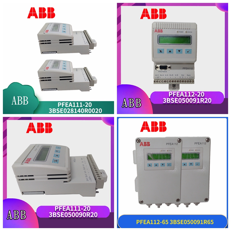
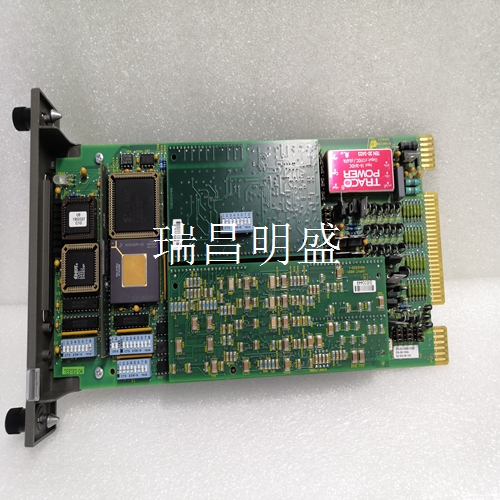
6240BP10831B-K 工控模块备件
电源错误IP 20版本(未密封):
当连接到24 VDC电源时,端子X1:1和X1:2之间的电压应为18-36 V。•如果电压低于18 V:–检查电源额定值。额定值应为18-36 V DC检查电源是否有足够的容量。参见第2.6.2节电源装置中的电源要求。•如果电源有足够的容量,请检查电源和之间的布线和电缆电阻。•如果电源和布线正确,则张力电子设备可能存在缺陷。更换。IP 65版本(NEMA 4):•检查连接到端子X9:1和X9:2的电源电压。电源电压必须为:85-264 V AC(100 V-15%至240 V+10%)频率范围:45-65 Hz张力电子设备PFEA111/122,用户手册第6章故障追踪6-8 3BSE029380R0001 1.4称重传感器励磁错误•检查电缆是否正确连接到电子设备。•如果使用单侧测量,并且只有称重传感器A连接到电子设备,检查端子X1:7和X1:8之间是否连接了短路线。–关闭张力电子设备并测量端子X1:3和X1:9之间的电阻。电阻>8欧姆:检查电子设备和称重传感器之间的总电缆电阻不超过5欧姆。如果电缆电阻不超过5欧姆,请检查电缆和称重传感器。电阻小于7欧姆:如果布线正确,则电子设备可能存在缺陷。更换。2警告2.1 Profibus通信问题检查:•总线是否正确终止。•Profibus地址。•电缆和连接器。2.2同步问题检查电缆和屏蔽。如果布线正确,张力电子设备可能存在缺陷。更换。
如果一个测压元件出现故障
则更改为单侧测量如果一个测压元件出现了故障,则可以从标准滚动更改为单边测量。对于称重传感器连接,请参考附录B、C、D或E中的电缆图,了解安装中使用的称重传感器类型。根据出现故障的测压元件,执行以下操作:测压元件A出现故障:1.从张力电子设备上断开测压元件。2.将测压元件B的连接移动到连接测压元件A的端子上。3.在X1:7和X1:8之间连接测压元件励磁电路的短路线。测压元件B有故障:1.从张力电子设备上断开测压元件。2.在X1:7和X1:8之间连接称重传感器激励电路的短路线。更改称重传感器连接后,必须更改张力电子设备中的一个参数设置。使用下面的菜单从StandardRoll更改为SingleSide
Power supply error IP 20 version (unsealed):
When connected to a 24 VDC power supply, the voltage between terminals X1:1 and X1:2 should be 18-36 V. • If the voltage is below 18 V: – Check the power supply rating. The rating shall be 18-36 V DC Check whether the power supply has sufficient capacity. Refer to Section 2.6.2 Power Supply Unit for power requirements. • If the power supply has sufficient capacity, check the wiring and cable resistance between the power supply and. • If the power supply and wiring are correct, the tension electronics may be defective. Replace. IP 65 version (NEMA 4): • Check the supply voltage connected to terminals X9:1 and X9:2. The power supply voltage must be: 85-264 V AC (100 V-15% to 240 V+10%) Frequency range: 45-65 Hz Tension electronic equipment PFEA111/122, Chapter 6 of the user manual Fault tracking 6-8 3BSE029380R0001 1.4 Load cell excitation error • Check whether the cable is correctly connected to the electronic equipment. • If single side measurement is used and only load cell A is connected to the electronic equipment, check whether there is a short line between terminals X1:7 and X1:8. – Turn off the tension electronics and measure the resistance between terminals X1:3 and X1:9. Resistance>8 ohms: check that the total cable resistance between the electronic equipment and the load cell does not exceed 5 ohms. If the cable resistance does not exceed 5 ohms, check the cable and load cell. Resistance less than 7 ohms: If the wiring is correct, the electronics may be defective. Replace. 2 Warning 2.1 Profibus communication problem check: • Whether the bus is terminated correctly. • Profibus address. • Cables and connectors. 2.2 Check cables and shields for synchronization problems. If the wiring is correct, the tension electronics may be defective. Replace.
If a load cell fails
If a load cell fails, it can be changed from standard rolling to unilateral measurement. For load cell connections, refer to the cable diagrams in Appendices B, C, D, or E for the type of load cell used in the installation. Depending on the faulty load cell, do the following: Load cell A is faulty: 1. Disconnect the load cell from the tension electronics. 2. Move the connection of load cell B to the terminal connecting load cell A. 3. Connect the short circuit of the excitation circuit of the load cell between X1:7 and X1:8. Load cell B is faulty: 1. Disconnect the load cell from the tension electronics. 2. Connect the short circuit of the load cell excitation circuit between X1:7 and X1:8. After changing the load cell connection, a parameter setting in the tension electronics must be changed. Use the following menu to change from StandardRoll to SingleSide


