


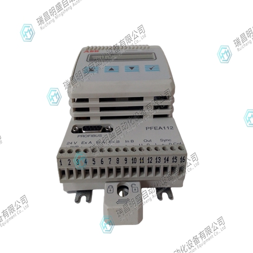
3BSE030369R0020张力传感器
干扰为了抗干扰,
称重传感器电缆应尽可能与噪声电源电缆分开。建议最小距离为0.3 m(12英寸)。如果测量系统电缆遇到噪声电缆,它们必须以直角交叉。1.3壁挂式IP 65版(NEMA 4)张力电子设备无需同步。如果两个或多个IP 20版本(未密封)张力电子设备安装在同一机柜中,则必须同步。通过互连所有装置的“SYNC”端子、螺钉端子X1:14和所有装置的螺钉端子X:15实现同步。必须使用双绞线或屏蔽电缆。如果关闭或移除一个单元,其余单元仍保持同步。图2-3.同步PFEA111/112 PFEA111/122 PFEA111/102 X1:15 14 14 PFEA111/112 1 23 14 n X1:15 X1:15 X1:15 X1:15 X1:15张力电子设备PFEA111-112的连接,用户手册第2节安装张力电子设备PFEA111/112 3BSE029380R0001 2-5 2安装张力电子产品PFEA111/12 2.1 IP 65版本(NEMA 4)电子设备安装在外壳中,用于墙壁安装。选择安装位置时,请检查是否有空间完全打开机柜盖。还要检查外壳前面是否有足够的工作空间。外壳配有六个电缆密封套。图2-4.安装尺寸mm(英寸)仰视图张力电子设备PFEA111/112,用户手册第2章安装2-6 3BSE029380R0001根据安装的称重传感器类型,根据附录(B、C、D或E)中的电缆图将电缆连接到端子。注:请勿将实心导线连接至端子。
不要将引脚压接到绞合芯上。
注:输入电源电压必须配备保险丝和张力电子设备外部的断开装置。张力电子设备PFEA111/112,用户手册第2节安装张力电子设备PFEA111/12 3BSE029380R0001 2-7 2.2 IP 20版本(未密封)图2-5。安装尺寸根据安装的称重传感器类型,根据附录(B、C、D或E)中的电缆图将电缆连接至端子。注:请勿将实心导线连接至端子。不要将引脚压接到绞合芯上。mm(英寸)(EN 50022-35x7,5或同等标准)张力电子设备PFEA111/112,用户手册第2章安装2-8 3BSE029380R0001 3接地为了无故障运行,必须小心接地。注意以下事项:•如果自由(未屏蔽)长度超过0.1 m(4 in.),则必须单独绞合各对电源和信号导线•外部保护接地(PE)电缆必须连接到其中一个接地棒螺钉夹上。•所有电缆屏蔽必须连接到接地棒,屏蔽连接的长度必须小于50 mm(2 in.)。注:电缆屏蔽必须仅在一端接地。•由于测量系统的信号接地连接到张力电子设备的底盘接地,因此连接到控制系统的上级系统的输入不得接地。图2-6和图2-7显示了互连测量系统和上级系统以实现最佳功能的最佳方式。图2-6。通过绝缘或差分输入连接上级系统图2-7。通过单独的绝缘放大器连接上级系统+0V-PFEA111/112 0V 0V 0V+-+PFEA111/122张力电子设备PFEA111/112,用户手册第2.5节连接称重传感器3BSE029380R0001 2-9 2.5连接称重传感器附录中给出了每个称重传感器类型的连接信息,见下表。附录PFCL 301E B PFCL 302E C PFRL 101 D PFTL 101 E张力电子设备PFEA111/112用户手册第2章安装2-10 3BSE029380R0001 2.6连接可选单元2.6.1绝缘放大器PXUB 201(仅适用于IP 20版本)当输入和输出之间进行电流绝缘时,使用绝缘放大器PYUB 201,或者在电源和输入/输出之间。参见第A.5.1节绝缘放大器PXUB 201。绝缘放大器PYUB 201拟安装在DIN导轨上。PXUB 201通过螺纹端子连接。PXUB 201通常由供应张力电子设备的相同+24 V直流电源供电。如果PXUB 201安装在端子组附近,则无需屏蔽张力电子设备和PXUB201之间的电缆。图2-8.绝缘放大器PXUB 201 2.6.2电源装置的典型连接如果没有24 V可用,则电源装置SD 821、SD 822和SD 823可用作IP 20版本的电源。所有三个电源装置的主电源电压为:•115 V AC(85-132 V)、100 V-15%至120 V+10%(电源电压选择单位为:•115 V AC(85-132 V),100 V-15%至120 V+10%
Interference To resist interference,
The load cell cable shall be separated from the noise power cable as far as possible. A minimum distance of 0.3 m (12 inches) is recommended. If the measuring system cables encounter noise cables, they must cross at right angles. 1.3 Wall mounted IP version 65 (NEMA 4) tension electronics do not need to be synchronized. If two or more IP 20 version (unsealed) tension electronics are installed in the same cabinet, they must be synchronized. Synchronization is achieved by interconnecting the "SYNC" terminals of all devices, screw terminals X1:14 and screw terminals X: 15 of all devices. Twisted pair or shielded cable must be used. If you close or remove one unit, the remaining units remain synchronized. Figure 2-3. Synchronizing the connection of PFEA111/112 PFEA111/122 PFEA111/102 X1:15 14 PFEA111/112 1 23 14 n X1:15 X1:15 X1:15 X1:15 X1:15 tension electronic equipment PFEA111-112, section 2 of the user manual Installing tension electronic equipment PFEA111/112 3BSE029380R0001 2-5 2 Installing tension electronic products PFEA111/12 2.1 IP version 65 (NEMA 4) Electronic equipment is installed in the enclosure for wall mounting. When selecting the installation location, check that there is space to fully open the enclosure cover. Also check that there is enough work space in front of the enclosure. The enclosure is equipped with six cable glands. Figure 2-4. Installation dimension mm (inch), bottom view, tension electronic device PFEA111/112. Installation in Chapter 2 of the User's Manual 2-6 3BSE029380R0001. According to the type of load cell installed, connect the cable to the terminal according to the cable diagram in Appendix (B, C, D or E). Note: Do not connect solid wires to terminals.
Do not crimp the pins onto the stranded core.
Note: The input power supply voltage must be equipped with fuse and disconnecting device outside the tension electronic equipment. Tension electronic device PFEA111/112, section 2 of the user manual Installing tension electronic device PFEA111/12 3BSE029380R0001 2-7 2.2 IP 20 version (unsealed) Figure 2-5. The installation dimension depends on the type of load cell installed, and the cable is connected to the terminal according to the cable diagram in Appendix (B, C, D or E). Note: Do not connect solid wires to terminals. Do not crimp the pins onto the stranded core. Mm (inch) (EN 50022-35x7,5 or equivalent standard) tension electronic equipment PFEA111/112, Chapter 2 of user manual Installation 2-8 3BSE029380R0001 3 Grounding In order to operate without fault, grounding must be done carefully. Note the following: • If the free (unshielded) length exceeds 0.1 m (4 in.), each pair of power and signal conductors must be twisted separately • The external protective grounding (PE) cable must be connected to one of the grounding rod screw clamps. • All cable shields must be connected to the grounding bar, and the length of the shield connection must be less than 50 mm (2 in.). Note: The cable shield must be grounded at one end only. • Since the signal ground of the measuring system is connected to the chassis ground of the tension electronics, the input to the superior system of the control system must not be grounded. Figure 2-6 and Figure 2-7 show the best way to interconnect the measurement system and the parent system to achieve optimal functionality. Figure 2-6. Connect the upper level system through insulation or differential input Figure 2-7. Connect the upper system+0V-PFEA111/112 0V 0V 0V+-+PFEA111/122 tension electronic equipment PFEA111/112 through a separate insulation amplifier. The connection information of each load cell type is given in the appendix of the user manual, section 2.5 Connecting load cells 3BSE029380R0001 2-9 2.5 Connecting load cells. See the following table. Appendix PFCL 301E B PFCL 302E C PFRL 101 D PFTL 101 E Tension Electronic Equipment PFEA111/112 User Manual Chapter 2 Installation 2-10 3BSE029380R0001 2.6 Connection Optional Unit 2.6.1 Insulation Amplifier PXUB 201 (only applicable to IP 20 version) When current insulation is conducted between input and output, insulation amplifier PYUB 201 is used, or between power supply and input/output. See Section A.5.1 Insulating Amplifier PXUB 201. The insulation amplifier PYUB 201 is to be mounted on a DIN rail. PXUB 201 is connected via threaded terminals. The PXUB 201 is normally powered by the same+24 V DC power supply that supplies the tension electronics. If the PXUB 201 is installed near the terminal block, it is not necessary to shield the cable between the tension electronics and the PXUB 201. Figure 2-8. Insulation amplifier PXUB 201 2.6.2 If 24 V is not available for typical connection of power supply unit, power supply units SD 821, SD 822 and SD 823 can be used as power supply for IP 20 version. Main power supply voltage of all three power supply units is: • 115 V AC (85-132 V), 100 V-15% to 120 V+10% (power supply voltage selection unit is: • 115 V AC (85-132 V), 100 V-15% to 120 V+10%
")
")
")

