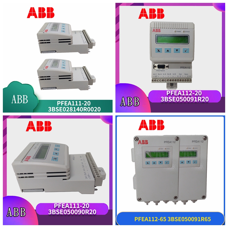
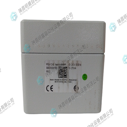
PFEA1120张力传感器
安装系统的方式
1关于本章您安装系统的方式对其功能、准确性和可靠性的影响比您想象的要大。安装越精确,测量系统越好。按照本章的说明,您将满足正确机械和电气安装的最重要要求。该设备是一种精密仪器,尽管用于恶劣的操作条件,但必须小心操作。2安全说明在开始任何安装工作之前,请阅读并遵循第1章“简介”中给出的安全说明。然而,如果地方法规更严格,则应优先考虑。3安装称重传感器安装要求和安装说明见:•附录B PFCL 301E-设计称重传感器安装•附录C PFTL 301E–设计称重传感器装置•附录D PFRL 101-设计称重元件装置•附录E PFTL 101-称重传感器装置张力电子装置PFEA111/112,用户手册第2章安装2-2 3BSE029380R0001 4安装电子单元4.1选择和布线4.1.1建议布线称重传感器和电子单元之间的布线和电气连接必须按照连接图3BSE08140D0065(请参阅附录了解您的称重传感器类型)或根据订单特定文档。图2-1。建议布线n×0.5 mm2+屏幕至控制系统主电源3×1.5 mm2接线盒称重传感器信号2×2×0.5 mm2+屏幕称重传感器激励2×5 mm2 4×1.0 mm2+屏幕最大50 m外部指示仪表(不包括在ABB交付中)称重传感器A称重传感器B PFEA111/112 IP 65版本Profibus DP(仅限PFEA112)电缆屏幕应连接至接近IP 20版本的接地棒(未密封)-安装在IP 65版本(NEMA 4)(NEMA 3)张力电子设备PFEA111/112外壳内的接地条,用户手册第4.1节选择和布线3BSE029380R0001 2-3•励磁电路中允许的最大电缆电阻如表2-1所示。
电缆电阻
调试前,检查称重传感器激励电路中的电缆电阻。•实心导线不应连接到端子上。引脚不应压接到绞合芯上。•称重传感器的电缆必须是坚固的四芯电缆,见图2-2。信号电路和励磁电路必须使用对角对。图2-称重传感器电缆中的芯线布置•接线盒和张力电子设备之间,信号和激励必须在单独的电缆中布线。例如:励磁用2×5 mm2电缆,称重传感器信号用带双绞线芯的屏蔽2×2×0.5 mm2电缆。•用于同步两个或多个张力电子设备的电缆必须经过屏蔽或双绞线。•张力电子设备和仪表或工艺设备之间的信号电缆必须为0.5 mm2屏蔽电缆。•电缆屏蔽必须连接到铜接地棒。屏幕连接最大长度为50 mm。•输入电源的保护接地导体必须连接到机柜中的铜接地棒。
How to install the system
1. The way you install the system in this chapter has a greater impact on its function, accuracy and reliability than you think. The more accurate the installation, the better the measurement system. Following the instructions in this chapter, you will meet the most important requirements for correct mechanical and electrical installation. This equipment is a precision instrument. Although it is used in harsh operating conditions, it must be operated with care. 2 Safety instructions Before starting any installation work, please read and follow the safety instructions given in Chapter 1 "Introduction". However, if local regulations are stricter, priority should be given. 3 For installation requirements and installation instructions of load cells, see: • Appendix B PFCL 301E – Design of Load Cell Installation • Appendix C PFTL 301E – Design of Load Cell Devices • Appendix D PFRL 101 – Design of Load Cell Devices • Appendix E PFTL 101 – Tension Electronic Device of Load Cell Devices PFEA111/112, Chapter 2 Installation of User Manual 2-2 3BSE029380R0001 4 Installation of Electronic Unit 4.1 Selection and Wiring 4.1.1 Recommended Wiring Wiring The wiring and electrical connection between the load cell and the electronic unit must be in accordance with the connection diagram 3BSE08140D0065 (please refer to the appendix for your load cell type) or specific documents according to the order. Figure 2-1. Recommended wiring n × 0.5 mm2+screen to main power supply 3 of control system × 1.5 mm2 junction box load cell signal 2 × two × 0.5 mm2+screen load cell excitation 2 × 5 mm2 4 × 1.0 mm2+screen max. 50 m external indicating instrument (not included in ABB delivery) Load cell A Load cell B PFEA111/112 Profibus DP version IP 65 (PFEA112 only) Cable screen should be connected to a ground bar close to the IP 20 version (unsealed) - a ground bar installed in the enclosure of the IP 65 version (NEMA 4) (NEMA 3) tension electronics PFEA111/112, Section 4.1 Selection and Wiring of 3BSE029380R0001 2-3 • The maximum cable resistance allowed in the excitation circuit is shown in Table 2-1.
Cable resistance
Before commissioning, check the cable resistance in the excitation circuit of the load cell. • Solid conductors shall not be connected to terminals. The pins should not be crimped to the stranded core. • The cable of the load cell must be a solid four core cable, as shown in Figure 2-2. Diagonal pairs must be used for signal circuits and excitation circuits. Figure 2 - Core arrangement in the load cell cable • Between the junction box and the tension electronics, the signal and excitation must be routed in separate cables. For example: 2 for excitation × 5 mm2 cable, shielding 2 with twisted pair core for load cell signal × two × 0.5 mm2 cable. • Cables used to synchronize two or more tension electronics must be shielded or twisted pair. • The signal cable between the tension electronic equipment and the instrument or process equipment must be 0.5 mm2 shielded cable. • The cable shield must be connected to a copper ground bar. The maximum length of the screen connection is 50 mm. • The protective grounding conductor of the input power supply must be connected to the copper grounding bar in the cabinet.


