


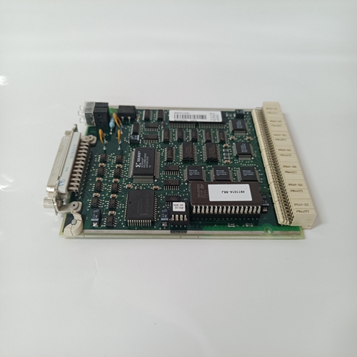
6007BG10000C控制器模块
输出驱动器
输出驱动器为用户提供热和涌流停机保护。在关闭驱动器之前,浪涌电流保护将允许高达990 mA的浪涌电流。该电流由所用灯泡的类型和数量决定。例如,两个40 mA 28 V灯丝灯泡可能具有高达960 mA((40 mA x 2)x 12=960 mA)的冷灯丝涌入电流。如果外部电路的涌入电流将超过990 mA限制,则应使用加温电阻器。这些电阻器应消耗使用中灯泡额定(热)电流的大约10%。对于上述示例,该电流为8 mA((40 mA x 2)x.1=8 mA)。电路板上为这些加温电阻器提供了SIP插座。这些电阻器必须为总线型,引脚1为公共。插座的针脚1接地。电子开关选项:可选的上拉电阻器可用于将输出驱动器置于电子开关配置中。这些开关输出由用户通过P2连接器供电。*数据极性:写入输出位的逻辑1将打开驱动晶体管。这产生逻辑0的输出。因此,逻辑1断言输出。这种数据极性称为正真。
内置测试:
该板设计有内部内置测试逻辑,支持除输出驱动器外的所有板载有源组件的测试。所有输出数据寄存器都具有读回功能。因此,用户可以监视写入该板的数据并确定其是否正常工作。提供前面板故障指示灯以帮助隔离故障板。此LED在通电时点亮,并且在用户定义的诊断软件成功完成后,可在程序控制下熄灭。物理/环境温度范围:0至+55°C,工作,-20至+85°C;储存湿度范围:20%至80%相对湿度,非冷凝高度:工作至10000英尺冷却:强制空气对流尺寸:双欧卡(6U),160 x 233.35 mm电源要求:3.0 A(典型值),5 V。用户必须为输出驱动器供电。该功率需求由用户负载决定。可以在前面板(P3或P4)或P2处进行连接。为了便于在P2处连接,提供了 P2电源附件,这是推荐的,但不是必需的。MTBF:162900小时(217F)警告:除非电路板上存在+5 VDC,否则不应向电路板施加用户提供的电压。应用-继电器驱动器灯驱动器电磁阀驱动器锤子驱动器步进电机驱动器SCR驱动器LED驱动器大电流、高压驱动器商标VMIC徽标是VMIC的注册商标。其他注册商标是其各自所有者的财产。
Output driver
The output driver provides users with heat supply and inrush shutdown protection. The surge current protection will allow up to 990 mA of surge current before shutting down the drive. This current is determined by the type and number of bulbs used. For example, two 40 mA 28 V filament bulbs may have cold filament inrush currents up to 960 mA ((40 mA x 2) x 12=960 mA). If the inrush current of the external circuit will exceed the 990 mA limit, a heating resistor should be used. These resistors shall consume approximately 10% of the rated (thermal) current of the bulb in use. For the example above, the current is 8 mA ((40 mA x 2) x 1=8 mA)。 SIP sockets are provided on the circuit board for these heating resistors. These resistors must be bus type with pin 1 common. The socket pin 1 is grounded. Electronic Switch Options: An optional pull-up resistor can be used to place the output driver in an electronic switch configuration. These switch outputs are powered by the user through the P2 connector* Data polarity: Logic 1 written to the output bit will turn on the drive transistor. This produces an output of logic 0. Therefore, logic 1 asserts output. This data polarity is called true.
Built in test:
The board is designed with built-in test logic, which supports the test of all on-board active components except the output driver. All output data registers have a read back function. Therefore, the user can monitor the data written to the board and determine whether it works normally. The front panel fault indicator is provided to help isolate the fault board. This LED lights up when powered on, and can be turned off under program control after the successful completion of user-defined diagnostic software. Physical/ambient temperature range: 0 to+55 ° C, working, - 20 to+85 ° C; Storage humidity range: 20% to 80% relative humidity, non condensing height: working to 10000 feet Cooling: forced air convection Size: double Okal (6U), 160 x 233.35 mm Power requirements: 3.0 A (typical), 5 V. The user must supply power to the output driver. The power demand is determined by the user load. It can be connected at the front panel (P3 or P4) or P2. To facilitate connection at P2, P2 power accessories are provided, which is recommended but not required. MTBF: 162900 hours (217F) Warning: Unless+5 VDC is present on the circuit board, the user supplied voltage should not be applied to the circuit board. Application - Relay driver Lamp driver Solenoid valve driver Hammer driver Stepper motor driver SCR driver LED driver High current, high voltage driver trademark VMIC logo is a registered trademark of VMIC. Other registered trademarks are the property of their respective owners.
")
")
")

