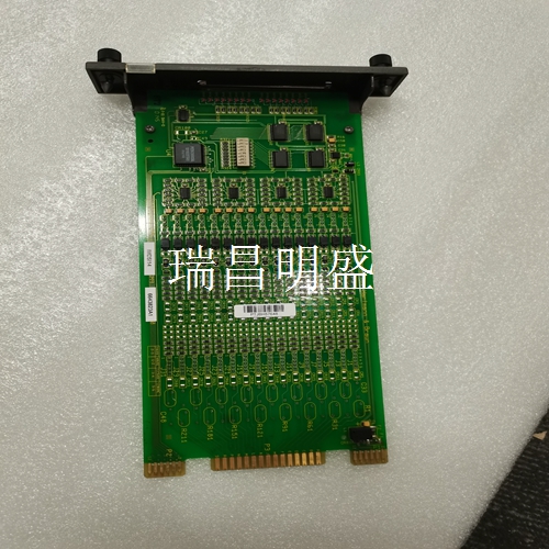
57520001-BZ DSCS116工控备件PLC模块DCS系统模块
正逻辑特性和负逻辑特性
输入特性该输入模块设计为具有正逻辑特性和负逻辑特性,因为它将输入设备的电流吸收或提供给用户公共线。如上所示,输入设备连接在电源总线和模块输入之间。该模块与多种输入设备兼容,例如:按钮、限位开关、选择器开关;电子接近开关,2线和3线。此外,该模块上的输入可由任何IC697 PLC电压兼容输出模块直接驱动。输入电路提供足够的电流以确保开关装置的可靠操作。在接通状态下,输入电流通常为10mA,在断开状态下可以接受高达2mA的泄漏电流,而无需接通。三线接近开关很容易应用,因为它们在接通状态提供低电压降,在断状态提供低泄漏电流。双线接近开关的电源来自信号连接;因此接通状态电压和断开状态泄漏电流都高于3线装置。该模块被设计为与许多这样的2线设备兼容;然而,必须仔细评估每种设备类型在ON和OFF状态下的兼容性。要确定与特定接近开关的兼容性,请在下图中找到开关的ON状态特性。如果该点落在输入负载线的左侧,则导通状态特性兼容。例如,在5伏电压降下,3mA的兼容接近开关的接通状态要求如下所示。如果接近开关泄漏小于2mA且模块输入电压为5伏或更低,则确保断开状态兼容性。
Positive logic characteristic and negative logic characteristic
Input characteristics The input module is designed with positive logic characteristics and negative logic characteristics, because it absorbs or provides the current of the input device to the user's common line. As shown above, the input device is connected between the power bus and the module input. The module is compatible with a variety of input devices, such as: buttons, limit switches, selector switches; Electronic proximity switch, 2-wire and 3-wire. In addition, the inputs on this module can be directly driven by any IC697 PLC voltage compatible output module. The input circuit provides sufficient current to ensure reliable operation of the switchgear. In the on state, the input current is usually 10mA, and in the off state, it can accept up to 2mA leakage current without connecting. Three wire proximity switches are easy to apply because they provide low voltage drop in the on state and low leakage current in the off state. The power supply of the two-wire proximity switch comes from the signal connection; Therefore, the on state voltage and the off state leakage current are higher than those of the 3-wire device. The module is designed to be compatible with many such 2-wire devices; However, the compatibility of each device type in the ON and OFF states must be carefully evaluated. To determine compatibility with a specific proximity switch, find the ON state characteristic of the switch in the following figure. If the point falls to the left of the input load line, the conduction state characteristics are compatible. For example, the on state requirements of a 3mA compatible proximity switch at a 5V drop are as follows. If the proximity switch leakage is less than 2 mA and the module input voltage is 5 volts or less, ensure off state compatibility.
输入滤波器
选择使用 PLC和某些其他CPU选项,该模块可配置为具有1mS或10mS输入滤波器。配置以模块为基础,而不是以点为基础;所有点具有相同的过滤时间。有关详细信息,请参阅适用的可编程控制器参考手册。中断当与 CPU一起使用时,输入点A1可配置为引起CPU中断。配置允许CPU在信号转换的上升沿或下降沿中断。中断响应不受输入滤波器时间选择的影响。有关详细信息,请参阅适用的可编程控制器参考手册。模块机械键控该模块包括一个机械键,可防止在给定插槽中一种模块类型意外替换另一种模块。该键适合连接器下方电路板上形状独特的区域。每个模块都有一个打包的密钥。首次安装模块时,钥匙锁在底板中央导轨上。拔出模块后,钥匙仍留在中央导轨中,将插槽配置为只接受相同的模块类型。如果在将钥匙锁在机架的中央导轨上后,需要更改模块在机架中的位置,则可以通过向上推动钥匙并将其从导轨上拔下,从而将其取下。然后,可以将其重新插入模块,并将模块插入机架中所需的位置。请注意,在 PLC机架中,只能将电源置于最左边的机架位置,插槽1(与电源相邻)必须始终包含CPU(机架0中-CPU机架)或总线接收器模块(扩展机架中)。
Input filter
Select Use PLC and some other CPU options, the module can be configured with 1mS or 10mS input filter. Configuration is based on modules, not points; All points have the same filter time. For details, refer to the applicable PLC reference manual. Interrupt When used with the CPU, input point A1 can be configured to cause a CPU interrupt. The configuration allows the CPU to interrupt on the rising or falling edge of the signal conversion. Interrupt response is not affected by input filter time selection. For details, refer to the applicable PLC reference manual. Module Mechanical Keying The module includes a mechanical key to prevent one module type from accidentally replacing another module in a given slot. This key is suitable for the uniquely shaped area on the circuit board below the connector. Each module has a packaged key. When installing the module for the first time, the key is locked on the central guide rail of the backplane. When the module is removed, the key remains in the central rail and the slot is configured to accept only the same module type. If you need to change the position of the module in the rack after locking the key on the central rail of the rack, you can remove the key by pushing it up and pulling it off the rail. You can then reinsert it into the module and insert the module into the desired location in the rack. Please note that in the PLC rack, the power supply can only be placed in the leftmost rack position, and slot 1 (adjacent to the power supply) must always contain the CPU (in rack 0 - CPU rack) or bus receiver module (in expansion rack).


