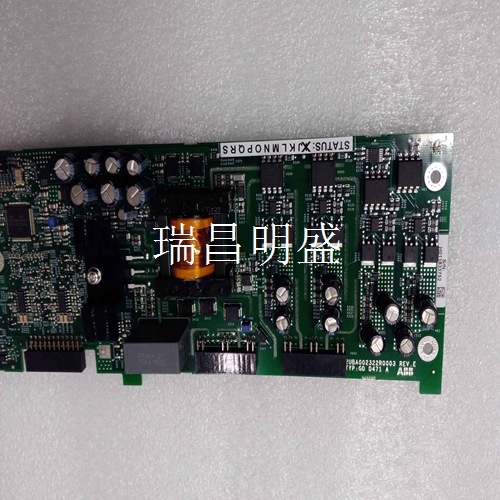
57520001-DX/1 卡件系统模块
跳线配置和位置
在主机板上安装之前,必须通过安装或移除跳线块E1上的跳线分流器来设置所需的节点ID。网络中的每个节点都必须具有唯一的节点ID,跳线块E2的位置参见第29页的图2-1。8个节点ID选择行允许从0到$FF(255十进制)的任何二进制节点ID。跳线块E1,引脚1和2对应于最低有效节点ID线,引脚15和16对应于最高有效节点ID。安装跳线分流器将二进制节点ID线设置为低(0),而移除跳线分路将二进制节点标识线设置为高(1)。下提供了可能的节点ID示例。
Jumper configuration and location
Before installing on the motherboard, you must set the required node ID by installing or removing the jumper shunt on the jumper block E1. Each node in the network must have a unique node ID. See Figure 2-1 on page 29 for the location of jumper block E2. Eight node ID selection rows allow any binary node ID from 0 to $FF (255 decimal). Jumper block E1, pins 1 and 2 correspond to the lowest valid node ID line, and pins 15 and 16 correspond to the highest valid node ID. Install the jumper shunt to set the binary node ID line to low (0), and remove the jumper shunt to set the binary node ID line to high (1). Examples of possible node IDs are provided under.
跳线E5配置在主机主板上安装之前
必须为适当的操作模式配置跳线E4。跳线E5控制板上的三个功能:1.引脚1和引脚2选择非冗余(快速)或冗余网络传输模式。2.引脚3和引脚4启用或禁用Rogue Master 0功能3.引脚5和引脚6启用或禁用Rogue Master1功能。引脚7和引脚8目前已保留,不应使用。第29页的表2-2详细说明了安装或拆除跳线分流器所选择的功能。出厂默认配置是安装了所有跳线分流器(引脚7和8除外)。
Before the jumper E5 is installed on the host motherboard
Jumper E4 must be configured for the appropriate operating mode. Three functions on the control board of jumper E5: 1. Pin 1 and pin 2 select non redundant (fast) or redundant network transmission mode. 2. Pin 3 and pin 4 enable or disable the Rogue Master 0 function 3. Pin 5 and pin 6 enable or disable the Rogue Master 1 function. Pins 7 and 8 are currently reserved and should not be used. Table 2-2 on page 29 details the functions selected to install or remove the jumper shunt. The factory default configuration is that all jumper shunts are installed (except pins 7 and 8).


