


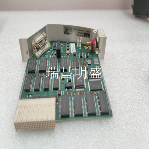
48980001-AG 电源转换器模块供应PLC系统备件
接地连接
检查机柜内的所有信号接线、电源和接地连接,以验证其完整性。检查连接时,务必仅沿拧紧方向转动螺钉、螺母或其他紧固装置。如果连接松动,则将其拧紧。如果连接紧固,拧紧操作将验证其是否牢固。不得有任何松动连接的动作。1.验证机柜内的所有电源连接是否牢固。2.验证终端装置或终端模块的所有现场接线连接是否牢固。警告警告机柜内有外露的交流和直流连接。这些暴露的电气连接存在电击危险,可能导致人身伤害或死亡。如果在电源输入面板上断开系统电源后,输入或输出电路存在电击危险,则包含这些外部供电电路的机柜门必须标有警告,说明存在多个电源。
如果确定DSI有故障
请更换新的DSI。不要试图修理模块;更换部件可能会影响模块性能。您可以在系统供电时卸下模块。更换模块:1.推动并转动两个前面板固定螺钉半圈,以解锁模块。当螺钉上的插槽垂直且插槽的开口端背离模块时,它将解锁。2.轻轻地将模块滑出MMU。3.配置更换模块开关和跳线设置。参考第3节中的地址选择开关(S1)和数字输入跳线设置。确保这些调整设置与原始模块相同。4.在与原始模块相同的插槽分配中,将更换模块与MMU中的导轨对齐;轻轻将其滑入,直到前面板与MMU框架的顶部和底部齐平,并且模块完全固定在连接终端设备的电缆中。5.推动并转动模块面板上的两个固定螺钉半圈至锁定位置。当螺钉上的插槽垂直且开口端朝向模块中心时,它将被锁定。6.恢复正常运行。
Ground connection
Check all signal wiring, power and ground connections in the cabinet to verify their integrity. When checking connections, be sure to turn screws, nuts or other fastening devices only in the tightening direction. If the connection is loose, tighten it. If the connection is tight, the tightening operation will verify that it is secure. No loose connection is allowed. 1. Verify that all power connections in the cabinet are secure. 2. Verify that all field wiring connections of the terminal unit or terminal module are secure. Warning There are exposed AC and DC connections in the warning cabinet. These exposed electrical connections present an electrical shock hazard that may result in personal injury or death. If there is a risk of electric shock in the input or output circuits after the system power is disconnected on the power input panel, the cabinet door containing these external power supply circuits must be marked with a warning that multiple power supplies exist.
If you determine the DSI is faulty
replace it with a new one. DO NOT try to repair the module; replacing components may affect the module performance. You can remove the module while system power is supplied. To replace a module: 1. Push and turn the two front panel captive retaining screws one half turn to unlatch the module. It is unlatched when the slots on the screws are vertical and the open end of the slots face away from the module. 2. Gently slide the module out of the MMU. 3. Configure the replacement module switch and jumper settings. Refer to Address Selection Switch (S1) and Digital Input Jumper Settings in Section 3. Make certain these adjustments are set the same as the original module. 4. In the same slot assignment as the original module, align the replacement module with the guide rails in the MMU; gently slide it in until the front panel is flush with the top and bottom of the MMU frame and and the module is fully seated in the cable to the termination device. 5. Push and turn the two captive retaining screws on the module faceplate one half turn to the latched position. It is latched when the slots on the screws are vertical and the open ends face the center of the module. 6. Return to normal operation.
")
")
")
")

