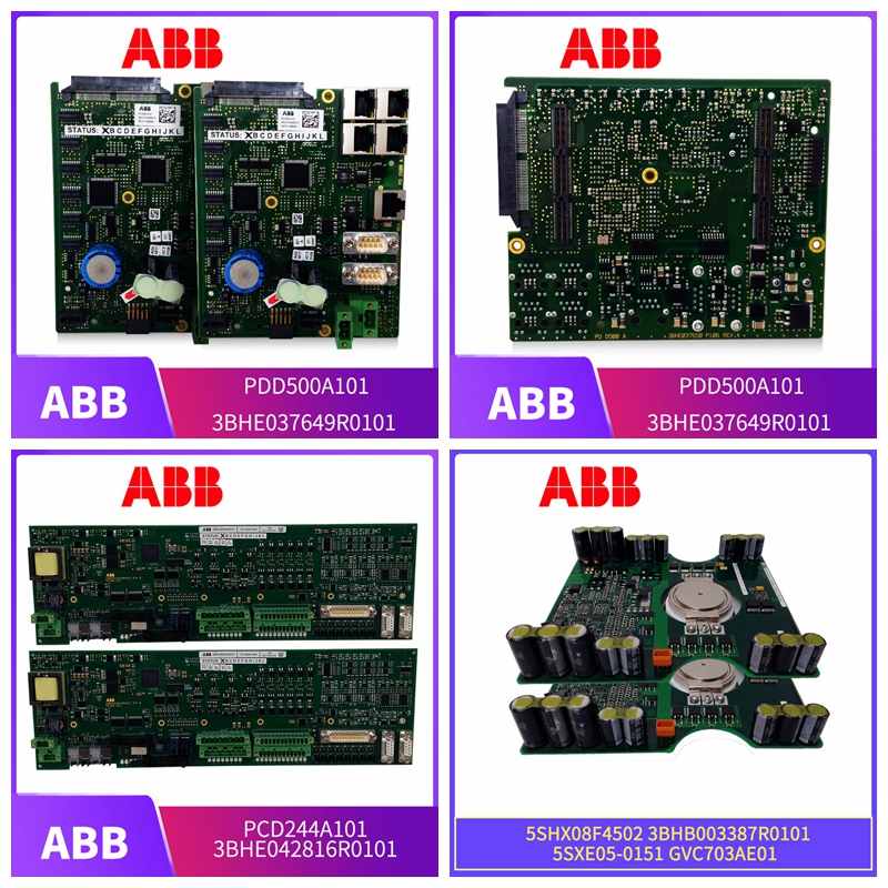
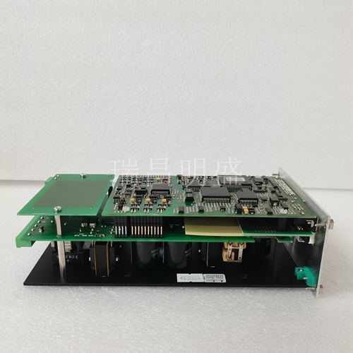
DSSB120 48980002-A 分布式基站控制器 ABB
模块安装单元
DSI模块插入标准INFI 90 OPEN模块安装单元(MMU)并占据一个插槽。要安装:1.验证模块的插槽分配。2.验证I/O模块和控制模块之间的MMU背板上的I/O扩展器总线插槽中是否有双列直插式测试。3.对于TU或TM设备,将终端电缆的带帽端从TU或TM连接到MMU背板。为此,将连接器插入与分配给数字输入模块的插槽相同的插槽中的背板插槽。插销应牢固卡入到位。4.将数字输入模块与MMU中的导轨对齐;轻轻滑入模块,直到前面板与MMU框架的顶部和底部齐平,并且模块位于终端设备的电缆中。5.推动并转动模块面板上的两个固定螺钉半圈至锁定位置。当螺钉上的插槽垂直且开口端朝向模块中心时,它将被锁定。
边缘连接器
布线连接和布线DSI有三个卡边缘连接器,用于提供逻辑电源、建立I/O扩展器总线通信和提供数字输入(分别为P1、P2、P3)。接线在MMU中安装模块将数字输入模块连接到P1处驱动电路所需的逻辑电源(+5 VDC)。它还将P2连接到I/O扩展器总线,以便与控制模块通信。P1和P2连接不需要额外的布线或布线。注:您必须在MMU的底板上安装双列直插式测试仪,以便在数字输入模块和控制模块之间连接I/O扩展器总线。定位模块,使总线能够连接模块,否则模块无法通信。电缆连接IMDSI1数字输入模块可以使用NTDI01终端单元或NIDI01终端模块进行终端。确定与TU或TM一起使用的电缆。
Module installation unit
The DSI module is inserted into a standard INFI 90 OPEN module installation unit (MMU) and occupies a slot. To install: 1. Verify the slot assignment of the module. 2. Verify whether there is a dual in-line test in the I/O expander bus slot on the MMU backplane between the I/O module and the control module. 3. For TU or TM devices, connect the capped end of the terminal cable from the TU or TM to the MMU backplane. To do this, insert the connector into the backplane slot in the same slot as the slot assigned to the digital input module. The latch should be firmly seated. 4. Align the digital input module with the guide rail in the MMU; Gently slide the module in until the front panel is flush with the top and bottom of the MMU frame and the module is in the cable of the terminal device. 5. Push and turn the two fixing screws on the module panel half a turn to the locked position. When the slot on the screw is vertical and the open end faces the center of the module, it will be locked.
Edge connector
Cabling Connections and Cabling DSI has three card edge connectors that provide logical power, establish I/O expander bus communications, and provide digital inputs (P1, P2, P3, respectively). Wiring Install the module in the MMU to connect the digital input module to the logical power supply (+5 VDC) required for the drive circuit at P1. It also connects P2 to the I/O expander bus for communication with the control module. P1 and P2 connections do not require additional wiring or cabling. Note: You must install a dual in-line tester on the MMU backplane to connect the I/O expander bus between the digital input module and the control module. Locate the module so that the bus can connect the module, otherwise the module cannot communicate. The cable connection IMDSI1 digital input module can be terminated with NTDI01 terminal unit or NIDI01 terminal module. Refer to Figure 3-3 to determine the cable to be used with TU or TM.
