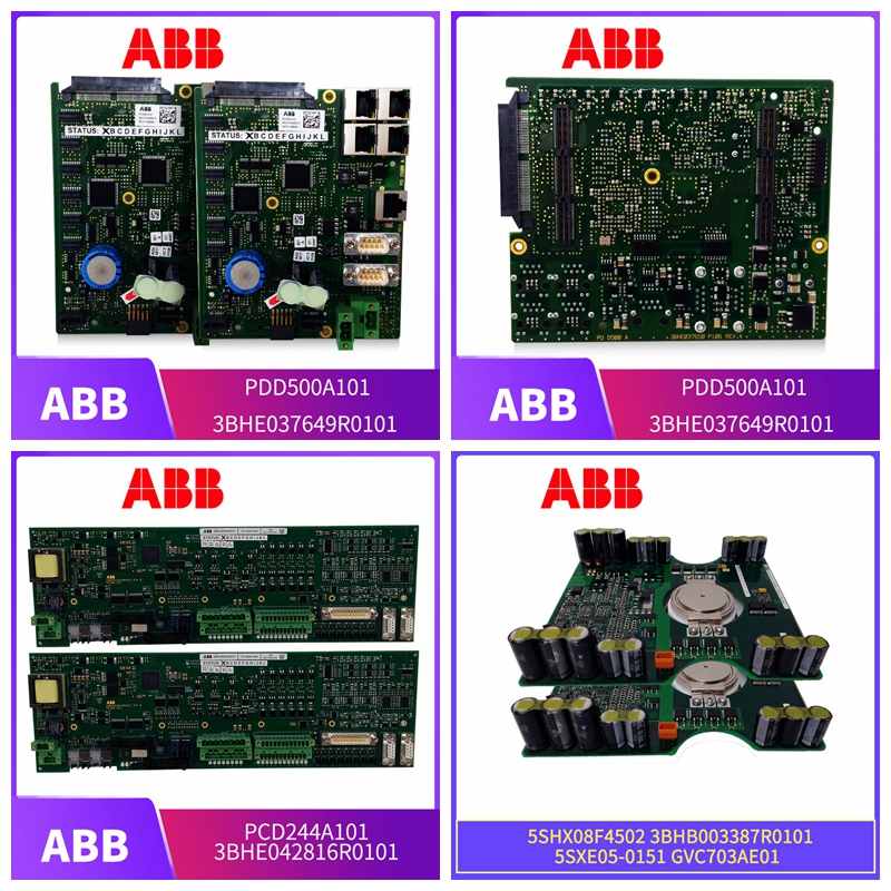
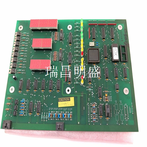
57310255-AX DSRF181A工控自动化备件卡件模块
输入信号路径
输入信号路径和低隔离电容允许防止快速瞬态突发干扰。阈值检测块电路测试输入电压以确定其是否处于指示ON或OFF状态的适当电压电平。该比较器的输出被发送到控制逻辑块中的读缓冲器。如果输入通电,也会导致前面板上相应的输入状态LED亮起。控制逻辑块由保存输入和状态字节值的缓冲器组成。I/O扩展器总线接口允许控制模块读取这些字节。输入电路说明当输入信号处于适当的电压电平时,齐纳二极管导通(接通),使电流流过光耦。可配置跳线(在IMDSI12上)或固定电阻器(在IMDS I13、IMDSI14或IMDSI15上)选择开启阈值和输入电压。光耦输出导致比较器输出变低。这将点亮模块前面板上的相应状态LED,以指示通电输入;I/O扩展器总线接口将逻辑1传输到I/O扩展机总线上的控制模块。当没有输入信号时,没有电流流过光耦。前面板LED不亮,DSI在总线上传输逻辑0。 显示了数字输入电路。
终端电缆
输入电路连接触点输入信号通过终端单元或终端模块的终端电缆连接到30针卡边缘连接器(P3) 。控制模块配置中的控制逻辑功能代码(FC)84访问I/O扩展器总线上的DSI。它还允许控制模块从DSI自动读取点(输入)数据或状态数据。该数据由缓冲电路(控制逻辑)输出到I/O扩展器总线接口(图2-1)。FC 84中的I/O地址必须与地址双列直插式开关(S1)上设置的地址相同。点数据字节点数据是两个8位字节。每个字节对应于A组或B组输入。每一位数据代表一个输入。该位值反映了该输入的状态,即打开(逻辑0)或关闭(逻辑1)。
Input signal path
The input signal path and low isolation capacitance allow protection against rapid transient bursts of interference. The threshold detection block circuit tests the input voltage to determine whether it is at the appropriate voltage level indicating an ON or OFF state. The output of the comparator is sent to the read buffer in the control logic block. If the input is powered on, it will also cause the corresponding input status LED on the front panel to light up. The control logic block consists of buffers that hold the input and status byte values. The I/O expander bus interface allows the control module to read these bytes. The input circuit shows that when the input signal is at an appropriate voltage level, the zener diode is turned on (on), allowing the current to flow through the optocoupler. The configurable jumper (on IMDSI12) or fixed resistor (on IMDS I13, IMDSI14, or IMDSI15) selects the ON threshold and input voltage. The optocoupler output causes the comparator output to become low. This will light the corresponding status LED on the front panel of the module to indicate the power on input; The I/O expander bus interface transfers logic 1 to the control module on the I/O expander bus. When there is no input signal, no current flows through the optocoupler. The front panel LED is not lit, and DSI transmits logic 0 on the bus. Shows the digital input circuit.
terminal cable
Input circuit connection contact The input signal is connected to the 30 pin card edge connector (P3) through the terminal cable of the terminal unit or terminal module. The control logic function code (FC) 84 in the control module configuration accesses the DSI on the I/O expander bus. It also allows the control module to automatically read point (input) data or status data from the DSI. This data is output by the buffer circuit (control logic) to the I/O expander bus interface (Figure 2-1). The I/O address in FC 84 must be the same as the address set on the address dipswitch (S1). The point data word node data is two 8-bit bytes. Each byte corresponds to Group A or Group B input. Each bit of data represents an input. This bit value reflects the status of the input, i.e., on (logic 0) or off (logic 1).


