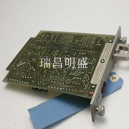
21660559-H DSRA110工控模块卡件PLC/DCS备件模块
电容器阻抗
3详细设计程序3.1输入电容器对于所有5-V、12-V和15-V输入电压设计,选择2.2-μF低ESR陶瓷输入电容器,以确保良好的启动性能。24V输入应用只需要0.47μF的输入电容。3.2输出电容器对于任何DCP02设计,选择1.0-μF低ESR陶瓷输出电容器以减少输出纹波。3.3 SYNC引脚在独立应用程序中,保持SYNC引脚浮动。4 PCB设计-尽可能通过使用相互接地和电源平面(轨道)将铜损耗(电阻和电感)降至最低。如果不可能,请使用宽轨道来减少损失。如果多个设备由同一电源供电,则必须部署轨道的星形连接系统;设备不得串联,因为这将级联电阻损耗。去耦电容器的位置很重要。它们必须尽可能靠近设备,以减少损失。有关更多详细信息,请参阅PCB布局部分。5去耦陶瓷电容器由于内部等效串联电阻(ESR)和较小程度的等效串联电感(ESL),所有电容器都有损耗。ESL的值并不总是容易获得的。然而,一些制造商提供了频率与电容器阻抗的关系图。 表通常显示电容器阻抗随频率增加而下降(如图15所示)。在图15中,XC是电容引起的电抗,XL是ESL引起的电抗,f0是谐振频率。随着频率的增加,阻抗停止下降并开始上升。最小阻抗点表示电容器的谐振频率。该频率是电容和电感电抗分量大小相等的频率。超过这一点,电容器作为电容器是无效的。
输入电容器
输入电容器和ESR的影响如果输入去耦电容器不是陶瓷(且ESR大于20mΩ), 然后在功率晶体管接通的瞬间,输入引脚的电压瞬间下降。如果电压降至约4 V以下,DCP将检测到欠压状态,并将DCP驱动电路切换到断开状态。执行此检测是为了预防真正的低输入电压情况,这种情况可能会减慢甚至停止内部电路正常工作。减速或停止会导致驱动晶体管导通时间过长,导致变压器饱和和设备损坏。在检测到低输入电压条件后,设备关闭内部驱动电路,直到输入电压返回到安全值,此时设备尝试重新启动。如果输入电容器仍无法维持输入电压,则再次发生停机。此过程重复进行,直到输入电容器充电到足以正确启动设备。正常启动应在设备通电后约1毫秒内发生。如果遇到相当长的启动持续时间,很可能是输入电源或电容器(或两者)没有充分工作。对于5-V至15-V输入设备,2.2-μF低ESR陶瓷电容器可确保良好的启动性能。对于24V输入电压器件,建议使用0.47μF陶瓷电容器。不建议使用钽电容器,因为大多数电容器的ESR值不低,会降低性能。
Capacitor impedance
3 Detailed design procedure 3.1 Input capacitor For all 5-V, 12-V and 15-V input voltage design, select 2.2- μ F Low ESR ceramic input capacitor to ensure good starting performance. Only 0.47 is required for 24V input applications μ Input capacitance of F. 3.2 Output capacitor For any DCP02 design, select 1.0- μ F Low ESR ceramic output capacitor to reduce output ripple. 3.3 SYNC pin Keep SYNC pin floating in independent application program. 4 PCB design - Minimize copper losses (resistance and inductance) as much as possible by using mutual grounding and power planes (rails). If this is not possible, use wide rails to reduce losses. If multiple equipment are powered by the same power supply, the star connection system of the track must be deployed; The equipment shall not be connected in series as this will cause cascading resistance losses. The position of the decoupling capacitor is important. They must be as close to the equipment as possible to reduce losses. For more details, see the PCB layout section. 5. Due to the internal equivalent series resistance (ESR) and smaller equivalent series inductance (ESL) of decoupling ceramic capacitors, all capacitors have losses. The value of ESL is not always easy to obtain. However, some manufacturers provide graphs of frequency versus capacitor impedance. The table usually shows that the capacitor impedance decreases with increasing frequency (as shown in Figure 15). In Figure 15, XC is the reactance caused by capacitance, XL is the reactance caused by ESL, and f0 is the resonant frequency. As the frequency increases, the impedance stops decreasing and starts to rise. The minimum impedance point represents the resonant frequency of the capacitor. This frequency is the frequency with equal capacitance and inductance reactance components. Beyond this point, capacitors are invalid as capacitors.
Input capacitor
Influence of input capacitor and ESR If the input decoupling capacitor is not ceramic (and the ESR is greater than 20m Ω), then the voltage of the input pin drops instantaneously when the power transistor is turned on. If the voltage drops below about 4 V, the DCP will detect the undervoltage state and switch the DCP drive circuit to the off state. This detection is performed to prevent a true low input voltage condition, which may slow down or even stop the normal operation of the internal circuit. Decelerating or stopping will cause the drive transistor to turn on for a long time, leading to transformer saturation and equipment damage. After the low input voltage condition is detected, the device closes the internal drive circuit until the input voltage returns to a safe value, and then the device attempts to restart. If the input capacitor still cannot maintain the input voltage, the shutdown occurs again. This process is repeated until the input capacitor is charged enough to properly start the device. Normal startup shall occur within about 1ms after the equipment is powered on. If a considerable starting duration is encountered, it is likely that the input power supply or capacitor (or both) is not working adequately. For 5-V to 15-V input devices, 2.2- μ F Low ESR ceramic capacitors ensure good starting performance. 0.47 is recommended for 24V input voltage devices μ F Ceramic capacitor. Tantalum capacitors are not recommended, because most capacitors have high ESR values, which will degrade their performance.


