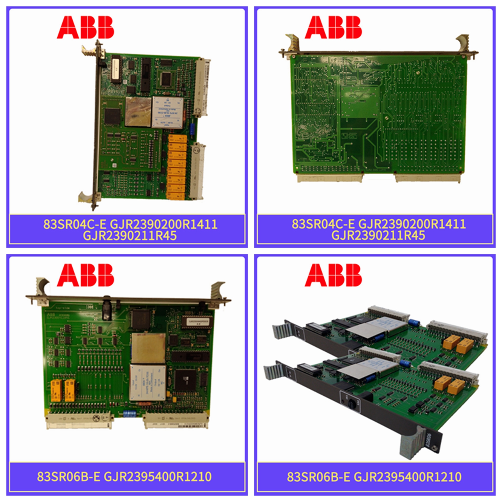
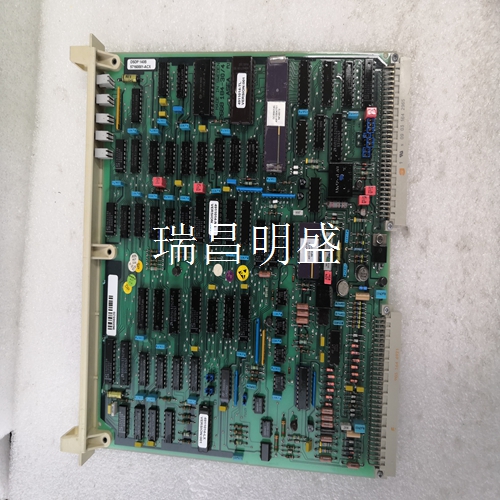
57310001-CX DSPC155工控系统系列产品卡件模块
预期用途模拟输入/输出模块
预期用途模拟输入/输出模块07 AC 91用作CS31系统总线上的远程模块。它包含16个模拟输入/输出通道,可在两种操作模式下配置:•操作模式“12位”:8个输入通道,可单独配置±10 V或0…20 mA,12位分辨率加8个输出通道,单独配置±10V或0?20 mA,12-位分辨率•操作模式:“8位”:16个通道,可成对配置为输入或输出,0…10 V或0…20 mA,8位分辨率•配置设置为DIL开关。•PLC提供用于测量4…20 mA信号的互连元件ANAI4_20(参见907 PC 331,连接元件库)。模块07 AC 91在CS31系统总线上使用最多八个输入字加上最多八个输出字。在操作模式“8位”中,2个模拟值被打包为一个字。该装置的工作电压为24 V DC。CS31系统总线连接与模块的其余部分电气隔离。该模块提供多种诊断功能(请参阅“诊断和显示”一章)。前面板上的显示和操作元件1 8个用于通道选择和诊断的绿色LED 2 8个用于信道模拟值显示的绿色LED 3与LED相关的诊断信息列表,当LED用于诊断时显示4个用于错误信息的红色LED 5测试按钮
电气连接模块
电气连接模块可安装在DIN导轨(15 mm高)上或使用4个螺钉。下一页的图显示了输入/输出模块的电气连接。2 07 AC 91 5.4-2 Hardware Advant Controller 31/发布日期:2001年5月5日图片5.4-2:模拟输入/输出模块的电气连接07 AC 91警告:控制系统的接地概念中必须包括过程电压(例如,负极端子的接地)。所有模拟值传感器和接收器的连接必须与其安装环境电气隔离。模拟布线的电缆屏蔽必须在进入机柜的地方连接到机柜接地。使用DIL开关设置模块地址和配置模拟通道
Intended purpose The analog input/output module
Intended purpose The analog input/output module 07 AC 91 is used as a remote module on the CS31 system bus. It contains 16 analog input/output channels that can be configured in two operating modes: • Operating mode "12 bits": 8 input channels, individually configurable ±10 V or 0...20 mA, 12 bit resolution plus 8 output channels, individually configurable ±10 V or 0...20 mA, 12 bit resolution • Operating mode "8 bits": 16 channels, configurable in pairs as inputs or outputs, 0...10 V oder 0...20 mA, 8 bit resolution • The configuration is set with DIL switches. • The PLC offers an interconnection element ANAI4_20 for measuring signals of 4...20 mA (refer to 907 PC 331, connection element library). The module 07 AC 91 uses up to eight input words on the CS31 system bus plus up to eight output words. In the operating mode "8 bits", 2 analog values are packed into one word. The operating voltage of the unit is 24 V DC. The CS31 system bus connection is electrically isolated from the rest of the module. The module offers a number of diagnosis functions (see chapter "Diagnosis and displays"). Displays and operating elements on the front panel 1 8 green LEDs for channel selection and diagnosis 2 8 green LEDs for analog value display of a channel 3 List of diagnosis information relating to the LEDs, when they are used for diagnosis display 4 Red LED for error messages 5 Test button
Electrical connection module
The electrical connection module can be mounted on a DIN rail (15 mm high) or with four screws. The diagram on the next page shows the electrical connections of the I/O module. 2 07 AC 91 5.4-2 Hardware Advanced Controller 31/Release date: May 5, 2001 Picture 5.4-2: Electrical connection of analog I/O module 07 AC 91 Warning: The grounding concept of the control system must include the process voltage (for example, the grounding of the negative terminal). All analog value sensor and receiver connections must be electrically isolated from the environment in which they are installed. The cable shield of analog wiring must be connected to the cabinet grounding at the place where it enters the cabinet. Use DIL switches to set module addresses and configure analog channels


