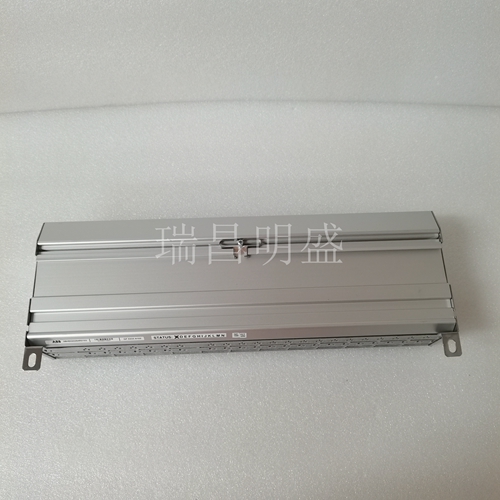
技术数据Modbus接口
协议Modbus RTU传输速率1200…115200 Bd(出厂设置19200 Bd偶数)布线RS485双线总线,总线/线路拓扑中的均压电缆供电工作电压范围20…28 V AC/DC(SELV)电流消耗200 mA(AC)/75 mA(DC)相对占空比100%输入电压输入30 V AC/D高信号识别>8 V AC/D输出输出触点2个转换触点开关电压最大250 V AC连续电流最大16 A/继电器(80 A/20 ms)所有触点的总电流25 A外壳尺寸WxHxD 2.0 x 2.8 x 3.0英寸。(50 x 70 x 75 mm)重量126 g安装位置根据IEC 60715,任何安装标准导轨TH35串联安装,无空间连接的最大模块数量限制为15个,或每次连接到电源的最大功耗为2安培(AC或DC)。对于任何类似的附加模块块,必须单独连接电源。材料外壳聚酰胺6.6 V0接线板聚酰胺6.6V0盖板聚碳酸酯保护型(IEC 60529)外壳IP40接线板IP20接线板电源和母线4极接线板最大AWG 16(1,5 mm²)实线最大。AWG 18(1.0 mm²)绞合线最小0.3 mm至最大1.4 mm(每个包装单元包括接线盒和跳线插头)模块连接输入/输出最大AWG 12(4.0 mm²。AWG 14(2.5 mm²)绞合线电线直径最小0.3 mm至最大2.7 mm温度范围操作-5°C…+55°C存储-20°C…+70°C保护电路极性反转保护工作电压极性反转电源和总线显示工作和总线活动绿色LED错误指示红色LED输入和输出黄色LED状态
安装设备
断电将模块安装在标准导轨上(接线盒和/或配电盘中符合IEC 60715的TH35)。安装电气安装和设备终端只能由合格人员进行,并遵守所有适用规范和法规。插入用于总线连接的端子板3 4 5 mm 5 6模块可以无间隙对齐。当模块串联安装时,使用跳线插头连接总线和电源电压。串联连接的最大模块数量限制为15个,或每次连接到电源的最大功耗为2安培(交流或直流)。对于任何类似的附加模块块,必须单独连接电源。连接总线电源的电缆,安装在系列7中。比特率和奇偶校验设置。当将转发器插入模块前盖后时,可以在编程模式下设置比特率和校验。此跳线在正常模式下拆下。比特率设置期间不需要连接到总线。模块的比特率可以通过以下方式设置:1.卸下模块的前盖;2.将跳线插入红色和绿色LED(a)之间的4极接头的两个中间引脚;3.根据下表,使用地址开关(-)设置所需的奇偶校验和比特率。4.打开模块的电源电压;它现在将比特率永久保存在EEPROM中;5.关闭模块的电源电压;6.从收割台上拆下跳线并放置前盖。如果设置与图表中指定的设置不同,则应用出厂设置。工厂设置:19200 Bd Eve
Technical Data Modbus Interface
Protocoll Modbus RTU Transmission rate 1200 ... 115200 Bd (factory setting 19200 Bd Even) Cabling RS485 two wire bus with voltage equalizing cable in bus / line topology Supply Operating voltage range 20 ... 28 V AC/DC (SELV) Current consumption 200 mA (AC) / 75 mA (DC) Relative duty cycle 100 % Input Voltage input 30 V AC/DC High-signal recognition >8 V AC/DC Output Output contacts 2 changeover contacts Switching voltage max. 250 V AC Continuous current max. 16 A / relay (80 A / 20 ms) Total current for all contacts 25 A Housing Dimensions WxHxD 2.0 x 2.8 x 3.0 in. (50 x 70 x 75 mm) Weight 126 g Mounting position any Mounting standard rail TH35 per IEC 60715 Mounting in series the maximum quantity of modules without space connected in line is limited to 15 or to a maximum power consumption of 2 Amps (AC or DC) per connection to the power supply. For any similar block of additional modules a separate connection to the power supply is mandatory. Material Housing Polyamide 6.6 V0 Terminal blocks Polyamide 6.6 V0 Cover plate Polycarbonate Type of protection (IEC 60529) Housing IP40 Terminal blocks IP20 Terminal blocks Supply and bus 4 pole terminal block max. AWG 16 (1,5 mm²) solid wireg max. AWG 18 (1,0 mm²) stranded wire Wire diameter min. 0.3 mm up to max. 1.4 mm (terminal block and jumper plug are included to each packing unit) Module connection Input/Output max. AWG 12 (4.0 mm²) solid wire max. AWG 14 (2.5 mm²) stranded wire Wire diameter min. 0.3 mm up to max 2.7 mm Temperature range Operation -5 °C ... +55 °C Storage -20 °C ... +70 °C Protective circuitry polarity reversal protection of operating voltage polarity reversal protection of supply and bus Display Operating and bus activity green LED Error indication red LED Status of the inputs & outputs yellow LED
Installation equipment
Power off to mount the module on standard rails (TH35 according to IEC 60715 in junction boxes and/or distribution boards). The installation of electrical installations and equipment terminations must only be carried out by qualified personnel and in accordance with all applicable codes and regulations. The terminal block 3 4 5 mm 5 6 modules inserted for bus connection can be aligned without gaps. When the modules are installed in series, use jumper plugs to connect the bus and power supply voltage. The maximum number of modules connected in series is limited to 15, or the maximum power consumption per connection to the power supply is 2 amperes (AC or DC). For any similar add-on block, the power supply must be connected separately. The cable connecting the bus power supply is installed in series 7. Bit rate and parity settings. When the repeater is inserted behind the front cover of the module, the bit rate and parity can be set in the programming mode. This jumper is removed in normal mode. It is not necessary to connect to the bus during bit rate setting. The bit rate of the module can be set in the following ways: 1. Remove the front cover of the module; 2. Insert the jumper into the two middle pins of the 4-pole connector between the red and green LED (a); 3. Use the address switch (-) to set the required parity sum bit rate according to the following table. 4. Turn on the power supply voltage of the module; It now permanently stores the bit rate in EEPROM; 5. Turn off the power supply voltage of the module; 6. Remove the jumper from the header and place the front cover. If the settings are different from those specified in the chart, the factory settings are applied. Factory setting: 19200 Bd Eve


