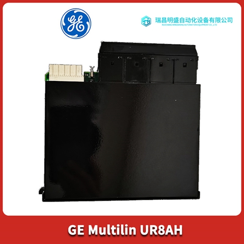
产品详情介绍
UR6TH继电保护器
操作原理4.1概述EMHP电源每相都连接有一个SCR模块。这些模块与点火电路和反馈回路(恒压/恒流“或”电路)一起工作。反馈回路确定SCR的点火角,确保向电力变压器的一次侧施加调节的交流输入电压。然后,通过电力变压器将该稳压交流电压调节至适当水平。经过全波整流和滤波后,产生恒定的输出电压或电流。4.2功率流本节讨论EMHP三相电源的功率和信号流的基本理论。如果用作第五节中提供的维护数据的补充,它将有助于隔离机组故障。阅读本节时,请参考图11,电源和信号流框图以及示意图#01-459-110和#01-142-000。对功率流的解释如下:通电后,交流电通过RFI滤波器、SCR网络的断路器CB1、K1。SCR模块每个模块包含两个反向并联连接的SCR。每个可控硅在阴极(输入交流电)同时施加负电压和栅极引线同时施加正电压时传导。在正半周期Q2、Q4和Q6期间进行,在负半周期Q1、Q3和Q5期间进行。门信号必须在1-3伏之间,SCR才能启动。SCR的点火角决定了施加到输入变压器的交流功率。因此,在输入循环早期触发的SCR的直流输出振幅提供了比在输入循环后期触发的更高的输出。
SCR与点火电路一起工作控制应用于电力变压器T1一次侧的交流功率。
该变压器将输入交流电压转换为负载电压和电流的适当交流电平。电压通过T1二次侧的整流器转换为DC。在高持续负载电流下,L1平均滤波器输入处的DC电压波形。在低负载电流下,电感无效,电容器C22改变为峰值脉冲幅度,以进行必要的滤波。输入波形的相位延迟在全额定输出时约为60度,在低输出电压和电流时约为180度。电阻器R10用作预负载,以确保负载与电源断开时的稳定性。偏置变压器T2有两个二次绕组。每个变压器上的端子4和6相对于中心抽头端子5产生50V RMS。这提供了两个相隔180度的正弦波信号,用于参考SCR点火电路的线频率。每个变压器的端子7和8之间产生20V RMS的电压。它们的电压在A100控制板上进行全波整流,为控制电路提供+和-15V DC。信号流用于调节该电源的所有控制电路位于A100控制板示意图#01-142-000上。信号流说明如下:来自偏置变压器T2的18-20伏交流电为A100控制盘的偏置部分提供三相输入。这些输入用于电源控制过程的不同方面。大多数电路使用由IC101和IC102调节的+15伏和-15伏直流电。IC101在150毫安负载下产生+15伏直流电,IC102在30毫安负载时产生-15伏负直流电。当使用干触点控制时,未调节的直流电压用于远程接通的电压。
PRINCIPLES OF OPERATION
4.1 GENERAL The EMHP power supply has a SCR module connected in each phase. These modules work in conjunction with the firing circuit and a feedback loop which is the constant voltage/constant current "ored" circuit. The feedback loop determines the firing angle of the SCRs, ensuring a regulated AC input voltage is applied to the primary of the power transformer. This regulated AC voltage is then adjusted to the proper level by the power transformer. After being full-wave rectified and filtered a constant output voltage or current is produced. 4.2 THE POWER FLOW This section discusses the basic theory of power and signal flow of the EMHP three phase power supply. If used as a supplement to the maintenance data provided in Section V, it will aid in isolation of unit faults. Refer to Figure 11, block diagram of power and signal flow plus schematics #01-459-110 and #01-142-000 when reading this section. Explanation of power flow is as follows: Upon applying power the AC passes through the RFI filter, circuit breaker CB1, K1 of the SCR networks. The SCR modules contain two SCRs per module, which are connected in reverse parallel. Each SCR conducts upon the simultaneous application of a negative voltage to its cathode (input AC) and a positive voltage to its gate lead. During the positive half cycle Q2, Q4 and Q6 is conducting and during the negative half cycle Q1, Q3 and Q5 will conduct. The gate signal must be from 1-3 volts for the SCR to fire. The firing angle of the SCR determines the amount of AC power applied to the input transformer. Thus the amplitude of the DC output of a SCR that is fired at an early point of the input cycle provides a higher output than one that is fired later in the input cycle.
The SCRs operating in conjunction with the firing circuits
controls the amount of AC power applied to the primary of power transformer T1. This transformer converts the input AC voltage to the appropriate AC level for the load voltage and current. The voltage is converted to DC by rectifiers on secondary side of T1. At a high continuous load current, L1 averages the DC voltage waveform at the input of the filter. At low load currents, the inductance is ineffective and capacitor C22 changes to peak pulse amplitude for necessary filtering. The phase delay of the input waveform ranges for approximately 60 degrees at the full rated output to nearly 180 degrees at low output voltage and current. Resistor R10 acts as a pre-load to assure stability when the load is disconnected from the power supply. The bias transformers T2 have two secondary windings. Terminals 4 and 6 on each transformer produces 50V RMS with respect to the center tap, terminal 5. This provides two sine wave signals spaced 180 degrees out of phase for referencing the SCR firing circuit to the line frequency. A voltage of 20V RMS is produced between terminals 7 and 8 of each transformer. Their voltages are full wave rectified on the A100 Control Board to provide + and -15V DC for control circuitry.SIGNAL FLOW All the controlling circuitry for regulation of this supply is located on the A100 Control Board schematic #01-142-000. Explanation of signal flow is as follows: The 18-20 volts AC from bias transformer T2 provides a three-phase input to the bias section of the A100 control board. These inputs are used for different facets of the controlling process of the power supply. Most of the circuitry use the + and -15 volts DC regulated by IC101 and IC102. IC101 produces a plus 15V DC with a 150 milliampere load and IC102 a minus 15VDC with a 30 milliampere load. The unregulated DC voltage is used for voltage with the remote turn-on when dry contact control is used.
产品优势
1:国外专业的供货渠道,具有价格优势
2:产品质量保证,让您售后无忧
3:全国快递包邮
4:一对一服务
公司主营范围简介
PLC可编程控制器模块,DCS卡件,ESD系统卡件,振动监测系统卡件,汽轮机控制系统模块,燃气发电机备件等,优势品牌:Allen Bradley、BentlyNevada、ABB、Emerson Ovation、Honeywell DCS、Rockwell ICS Triplex、FOXBORO、Schneider PLC、GE Fanuc、Motorola、HIMA、TRICONEX、Prosoft等各种进口工业零部件、欧美进口模块。
产品广泛应用于冶金、石油天然气、玻璃制造业、铝业、石油化工、煤矿、造纸印刷、纺织印染、机械、电子制造、汽车制造、塑胶机械、电力、水利、水处理/环保、锅炉供暖、能源、输配电等等


