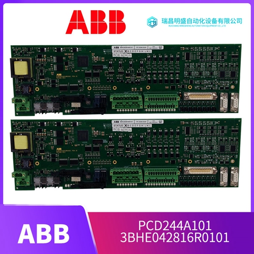
产品详情介绍
UAA326A04信号控制板
输入线应过大以便提供尽可能低的阻抗,因为会产生高峰值电流。输入线通过外壳后部的导管开口插入。拆除导管开口附近的盖板,即可接近输入接线端子。这些端子为压力连接器类型。使用足够重的导线将负载连接到POS和NEG输出端子,以防止输出端子和负载之间的IR大幅下降。遥感可用于补偿IR下降。参见第3.3.2段。注:两个输出端子都是浮动的,可以接地,也可以在底盘接地电压低于600V的任何电压下操作。出厂前,所有过压电路均已正确调整至各自的装置。对于小于最大输出电压的跳闸电平,或简单检查过电压电路:A.将电位计设置为顺时针方向。B.将电源输出电压调整为所需的跳闸电平。C、 逆时针缓慢调整电位计,直到OVP跳闸,关闭设置。一旦点燃,SCR将保持开启,直到阳极电压被移除(降低到其“开启”电平以下)或阳极电流降至最低“保持”电流以下。过电压范围为装置最大输出电压的50%至100%。如果上述任何事件没有发生,则电源有缺陷,不得运行。根据具体情况,需要进行本手册其他部分所述的保修服务或故障排除。
控制装置和指示器
前面板表面包含在正常模式下操作电源所需的所有控制装置和指示灯。以下检查程序描述了前面板控制装置和指示器的使用(图1,第3.3.1节),并确保电源正常工作。电源的初步检查是在未连接负载的情况下完成的。a、 如图1所示,检查装置背面的屏障跳线带是否处于正常模式。b、 完全逆时针设置所有控件。c、 将断路器(1)开/关开关转到“开”。风扇将立即启动。由于将出现软启动电路输出,在10-15秒延迟后按下启动按钮。d、 所有三相指示灯必须点亮。e、 前进电流控制(6)半圈,缓慢前进电压控制(3)。当此控制完全顺时针推进时,直流电压表(4)将从零偏转至电源的最大额定值。电压指示器(5)将点亮。f、 完全逆时针返回所有控件。g、 要检查恒定电流,首先关闭电源。将短路棒连接到电源背面的正负输出端子上。h。按下启动按钮。顺时针推进电压控制(3)一圈,然后缓慢推进电流控制(6)。顺时针推进此控制时,直流电流表(8)将从零平稳偏转至电源的额定电流。电流指示灯(7)将点亮。i、 完全逆时针返回所有控制装置并关闭装置。断开输出短路棒。3.1.1 OVP操作如果电源配备过电压撬杆,前面板将包含过电压调整(9)。该电位计可通过前面板上的检修孔进行调整。
The input wires should be oversized
so as to provide as low an impedance as practical, since high peak currents are drawn. Input wires are inserted through the conduit opening in the rear of the enclosure. Access to the input wiring terminals is made by removing the cover plate adjacent to the conduit opening. These terminals are of the pressure connector type. Connect the load to the POS and NEG output terminals using heavy enough leads to prevent substantial IR drops between the output terminals and the load. Remote sensing can be used to compensate for IR drops. See paragraph 3.3.2. NOTE: Both output terminals are floating and either may be grounded or operated at any voltage less than 600V with respect to chassis ground.All overvoltage circuitry has been properly adjusted to their respective unit before leaving the factory. For trip levels less than the maximum output voltage or to check the overvoltage circuitry simply: A. Set the potentiometer fully clockwise B. Adjust the power supply output voltage to the desired trip level. C. Slowly adjust the potentiometer counterclockwise until OVP trips turning off the set. Once fired, the SCRs remain on until the anode voltage is removed (decreased below its "on" level) or until anode current falls below a minimum "holding" current. The overvoltage range is from 50% to 100% of the maximum output voltage of the unit. If any of the above events does not occur, the supply is defective and must not be operated. Depending on circumstances either warranty service or troubleshooting as described elsewhere in this manual is required.
CONTROLS AND INDICATORS
The front panel surface contains all the controls and indicators necessary to operate the supply in its normal mode. The following checkout procedure describes the use of the front panel control and indicators (Figure 1, Section 3.3.1) and ensures that the supply is operational. This preliminary check of the power supply is done without a load connected. a. Check the barrier jumper straps on the back of the unit, as shown in Figure 1, for normal mode. b. Set all controls completely counterclockwise. c. Turn the CIRCUIT BREAKER (1) on/off switch to "on". The fans will start immediately. Push the Start Button after a 10-15 second delay due to the soft start circuit output will occur. d. All 3 Phase Indicators must be lit. e. Advance CURRENT CONTROL (6) one-half turn and slowly advance VOLTAGE CONTROL (3). The DC VOLTMETER (4) will deflect from zero to maximum rating of the supply as this control is advanced completely clockwise. The VOLTAGE INDICATOR (5) will be lit. f. Return all controls completely counterclockwise. g. To check out constant current, first turn-off supply. Connect a shorting bar across the plus and minus output terminal at the back of the power supply.h. Push the Start Button. Advance the VOLTAGE CONTROL (3) one turn clockwise and slowly advance the CURRENT CONTROL (6). The DC AMMETER (8) will deflect smoothly from zero to the rated current of the supply as this control is advanced clockwise. The CURRENT INDICATOR (7) will be lit. i. Return all controls completely counterclockwise and turn unit off. Disconnect output shorting bar. 3.1.1 OVP OPERATION If supply is equipped with an overvoltage crowbar, the front panel will contain OVERVOLTAGE ADJUSTMENT (9). This potentiometer may be adjusted through an access hole in the front panel.
产品优势
1:国外专业的供货渠道,具有价格优势
2:产品质量保证,让您售后无忧
3:全国快递包邮
4:一对一服务
公司主营范围简介
PLC可编程控制器模块,DCS卡件,ESD系统卡件,振动监测系统卡件,汽轮机控制系统模块,燃气发电机备件等,优势品牌:Allen Bradley、BentlyNevada、ABB、Emerson Ovation、Honeywell DCS、Rockwell ICS Triplex、FOXBORO、Schneider PLC、GE Fanuc、Motorola、HIMA、TRICONEX、Prosoft等各种进口工业零部件、欧美进口模块。
产品广泛应用于冶金、石油天然气、玻璃制造业、铝业、石油化工、煤矿、造纸印刷、纺织印染、机械、电子制造、汽车制造、塑胶机械、电力、水利、水处理/环保、锅炉供暖、能源、输配电等等


