


产品细节介绍
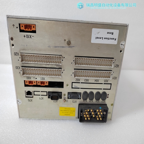
1VCF752000操作面板主机
电机数据表规定,允许的启动顺序为2冷或1热,之后必须等待5小时尝试再次启动。
•这意味着在正常启动条件下,电机使用34%到50%的热容量。因此,两个允许连续启动,但不允许三次(即34×3>100)。
•如果热/冷曲线或热/冷安全失速比不可用,程序0.5(1热/2冷启动)作为热/冷态比。
•编程启动抑制“开”可在62.5%(50×1.25)热容量可用时尽快重启。
•在2次冷启动或1次热启动后,将使用接近100%的热容量。使用的热容量呈指数衰减
(计算见369手册电机冷却部分)。1次后仅使用37%的热容量常数,这意味着有足够的热容量可用于另一次启动。计划60分钟(5小时)作为停止冷却时间常数。因此,在2次冷启动或1次热启动后,停止的电机将被阻止启动5次小时。
由于电机运行时转子冷却更快,因此运行冷却时间常数的合理设置可能为一半停止冷却时间常数或150分钟。使用的热容量计算过载元件使用热容量算法来确定过载跳闸条件。过载程度电流决定热存储器的填充速度,即如果电流刚好超过FLC×O/L传感器,则热容量缓慢增加;如果电流远远超过FLC拾取水平,则热容量会迅速增加。当使用的热容量达到100%时,发生过载跳闸。过载电流不一定要通过过载曲线才能发生跳闸。如果有热容量已经建立,过载跳闸将更快发生。换句话说,过载跳闸将在规定的仅当热容量等于零且电流以稳定速率应用时,曲线上的时间。否则热容量从过载前的值增加,直到达到100%热容量和过载发生跳闸。
正确选择过载曲线以进行适当保护很重要。在某些情况下,需要计算启动后形成的热容量。这样做是为了确保369在完成一个开始。热容量的实际填充是过载电流曲线下的面积。因此,到计算启动后的热容量,计算过载电流的积分。
下面是一个启动期间如何计算热容量的示例:
热容量计算:
1.画出与加速度曲线和过载曲线相交的线。这如图7-6所示:热第7-18页的极限曲线。
2.确定绘制线相交的时间、加速度曲线以及绘制线与所选过载曲线相交的时间。
3.整合已确定的值。369的启动抑制元件提供准确可靠的启动保护,而不会造成不必要的锁定时间延长,导致生产停机。锁定时间基于电机的实际性能和应用而不是在最坏的情况下,因为其他启动保护元素。
369热容量算法用于确定启动抑制元件的锁定时间。热容量为显示电机温度的百分比值,该值来自过载电流(以及不平衡电流和RTD(如果启用了各自的偏置功能)。了解Thermal最简单的方法369的建模功能是成像一个装有热容量的桶。一旦这个假想的铲斗装满,就会发生过载跳闸。铲斗由随时间累积的过载电流量填充,并与编程的过载曲线进行比较,以获得一个百分比值。热容量桶根据编程的当电流低于满载电流(FLC)并正常运行时的运行冷却时间
EXAMPLE
Motor data sheets state that the starting sequence allowed is 2 cold or 1 hot after which you must wait 5 hours before attempting another start. • This implies that under a normal start condition the motor is using between 34 and 50% thermal capacity. Hence, two consecutive starts are allowed, but not three (i.e. 34 × 3 > 100). • If the hot and cold curves or a hot/cold safe stall ratio are not available program 0.5 (1 hot / 2 cold starts) in as the hot/ cold ratio. • Programming Start Inhibit ‘On’ makes a restart possible as soon as 62.5% (50 × 1.25) thermal capacity is available. • After 2 cold or 1 hot start, close to 100% thermal capacity will be used. Thermal capacity used decays exponentially (see 369 manual section on motor cooling for calculation). There will be only 37% thermal capacity used after 1 time constant which means there is enough thermal capacity available for another start. Program 60 minutes (5 hours) as the stopped cool time constant. Thus after 2 cold or 1 hot start, a stopped motor will be blocked from starting for 5 hours. Since the rotor cools faster when the motor is running, a reasonable setting for the running cool time constant might be half the stopped cool time constant or 150 minutes.
THERMAL CAPACITY USED CALCULATION
The overload element uses a Thermal Capacity algorithm to determine an overload trip condition. The extent of overload current determines how fast the Thermal Memory is filled, i.e. if the current is just over FLC × O/L Pickup, Thermal Capacity slowly increases; versus if the current far exceeds the FLC pickup level, the Thermal Capacity rapidly increases. An overload trip occurs when the Thermal Capacity Used reaches 100%. The overload current does not necessarily have to pass the overload curve for a trip to take place. If there is Thermal Capacity already built up, the overload trip will occur much faster. In other words, the overload trip will occur at the specified time on the curve only when the Thermal Capacity is equal to zero and the current is applied at a stable rate. Otherwise, the Thermal Capacity increases from the value prior to overload, until a 100% Thermal Capacity is reached and an overload trip occurs. It is important to chose the overload curve correctly for proper protection. In some cases it is necessary to calculate the amount of Thermal Capacity developed after a start. This is done to ensure that the 369 does not trip the motor prior to the completion of a start. The actual filling of the Thermal Capacity is the area under the overload current curve. Therefore, to calculate the amount of Thermal Capacity after a start, the integral of the overload current most be calculated. Below is an example of how to calculate the Thermal Capacity during a start: Thermal Capacity Calculation: 1. Draw lines intersecting the acceleration curve and the overload curve. This is illustrated in Figure 7–6: THERMAL LIMIT CURVES on page 7–18. 2. Determine the time at which the drawn line intersect, the acceleration curve and the time at which the drawn line intersects the chosen overload curve. 3. Integrate the values that have been determined
The Start Inhibit element of the 369 provides an accurate and reliable start protection without unnecessary prolonged lockout times causing production down time. The lockout time is based on the actual performance and application of the motor and not on the worst case scenario, as other start protection elements. The 369 Thermal Capacity algorithm is used to establish the lockout time of the Start Inhibit element. Thermal Capacity is a percentage value that gives an indication of how hot the motor is and is derived from the overload currents (as well as Unbalance currents and RTDs if the respective biasing functions are enabled). The easiest way to understand the Thermal Modeling function of the 369 is to image a bucket that holds Thermal Capacity. Once this imaginary bucket is full, an overload trip occurs. The bucket is filled by the amount of overload current integrated over time and is compared to the programmed overload curve to obtain a percentage value. The thermal capacity bucket is emptied based on the programmed running cool time when the current has fallen below the Full Load Current (FLC) and is running normally
")
")
公司主营产品图展示
")
产品优势
1:国外专业的供货渠道,具有价格优势
2:产品质量保证,让您售后无忧
3:全国快递包邮
4:一对一服务
公司主营范围简介
PLC可编程控制器模块,DCS卡件,ESD系统卡件,振动监测系统卡件,汽轮机控制系统模块,燃气发电机备件等,优势品牌:Allen Bradley、BentlyNevada、ABB、Emerson Ovation、Honeywell DCS、Rockwell ICS Triplex、FOXBORO、Schneider PLC、GE Fanuc、Motorola、HIMA、TRICONEX、Prosoft等各种进口工业零部件、欧美进口模块。
产品广泛应用于冶金、石油天然气、玻璃制造业、铝业、石油化工、煤矿、造纸印刷、纺织印染、机械、电子制造、汽车制造、塑胶机械、电力、水利、水处理/环保、锅炉供暖、能源、输配电等等

