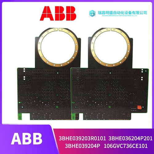
公司主营产品图展示

产品优势
1:国外专业的供货渠道,具有价格优势
2:产品质量保证,让您售后无忧
3:全国快递包邮
4:一对一服务
公司主营产品文字介绍
PLC可编程控制器模块,DCS卡件,ESD系统卡件,振动监测系统卡件,汽轮机控制系统模块,燃气发电机备件等,优势品牌:Allen Bradley、BentlyNevada、ABB、Emerson Ovation、Honeywell DCS、Rockwell ICS Triplex、FOXBORO、Schneider PLC、GE Fanuc、Motorola、HIMA、TRICONEX、Prosoft等各种进口工业零部件、欧美进口模块。
产品广泛应用于冶金、石油天然气、玻璃制造业、铝业、石油化工、煤矿、造纸印刷、纺织印染、机械、电子制造、汽车制造、塑胶机械、电力、水利、水处理/环保、锅炉供暖、能源、输配电等等
产品详情内容介绍
GNT0164000R0001驱动电源板
交换机设置两个拨动开关位于模块的左上角,用于确定与外部设备的通信类型。两个开关都是用户可选择。
1.纸盒/BCD开关
此切换开关确定输出数据是否由目标设备作为BCD或二进制值。
2.闪光灯激活高/低开关
此拨动开关允许为选通输出数据选择真高或真低。注:I/O映射选择、BCD/二进制开关设置端子编号和输出功能之间的关系用户连接到标准螺钉端子排。刚性接线系统允许在不干扰接线的情况下插入或移除模块。
下图显示了如何现场连接装置。上拉电阻器连接必须在有源设备端安装上拉电阻器才能使用B862输出单元上拉电阻的值取决于连接到数据总线,如下所述。每个输出满足0.4 V逻辑低时最大16 mA,逻辑高时最小3.3 V。如果超过电流限制,应调整上拉电阻值在规范范围内;否则,可能会获得虚假结果。
下图显示了电阻器在设备上的连接方式
终止对于由16条数据线组成的单个设备,需要16个1k电阻,或,每个数据线一个1k电阻。随着附加设备添加到数据总线上拉电阻的值必须增加1k。换句话说,如果两个设备使用时,上拉电阻必须为2k,三个设备需要3k上拉,并且以此类推,对于每个数据,最多8个设备需要8k上拉线上拉电阻器连接此诊断测试以1/s的速度执行,所需时间少于1ms在诊断过程中,输入无法检测到低或高状态,导致向控制器报告故障,活动LED闪烁。数字滤波对所有输入执行,以减少滋扰性故障的发生。模块和控制器之间的通信由四个字组成。二单词包含每个输入的状态,另外两个单词包含故障每个输入的状态。在状态字中,高或一表示打开条件。在故障状态字中,一个高或一个表示相应输入处存在故障。B863模块不仅读取24 Vdc输入,还允许您监控通过使用输入错误标志,检查输入电路的健康状况。在以下方面例如,网络允许您监视错误标志输入以进行维护和故障排除。如果B863模块的I/O映射为30001-30004,则寄存器30001和30002是真实世界的输入,30003和3004成为错误标志输入。
寄存器30003和30004与寄存器40011和40012的比较。
Switch Settings
Two toggle switches are located at the top left of the module and are used to determine the type of communication with external devices. Both switches are user selectable. 1. Bin/BCD Switch This toggle switch determines whether the output data is to be interpreted by the target devices as a BCD or a binary value. 2. Strobes Active Hi/Lo Switch This toggle switch allows selection of either true-hi or true-lo for strobing output data. NOTE: The relation between the I/O map selection, the BCD/binary switch setting Terminal Numbering and Output Functions User connections are made to a standard screw terminal strip. The rigid wiring system permits module insertion or removal without disturbing the wiring. The following illustration shows how to field connect the unit.The B863 module not only reads 24 Vdc inputs, but it allows you to monitor the health of the input circuits through the use of the input error flags. In the following example, networks allow you to monitor the error flag inputs for maintenance and troubleshooting. If the B863 module is I/O mapped as 30001-30004, then registers 30001 and 30002 are the real world inputs, and 30003 and 30004 become the error flag Inputs. Comparison of registers 30003 and 30004 to registers 40011 and 40012.
Pull-up Resistor Connection
Pull-up resistors must be installed at the active device end to use the B862 output module. The value of the pull-up resistor depends upon the number of devices that are attached to the data bus, as explained below. Each output meets 0.4 V maximum at 16 mA for a logic low and 3.3 V minimum at 16 mA for a logic high. If the current limit has been exceeded, the pull-up resistor values should be adjusted within specification; otherwise, spurious results may be obtained. The following illustration indicates how the resistors are connected at the device end. For a single device consisting of 16 data lines, 16 1 k resistors are required, or, one 1 k resistor per data line. As additional devices are added to the data bus, the value of the pull-up resistor must be increased by 1 k. In other words, if two devices are used, the pull-up resistor must be 2 k, three devices require a 3 k pull-up, and so on, with the maximum number of 8 devices requiring 8 k of pull-up for each data line. Pull-up resistor connection This diagnostic test is performed at a rate of 1/s, and takes less than 1 ms. The inability of an input to detect a low or high state during diagnostics, results in the reporting of a fault to the controller, and the flashing of the active LED. Digital filtering is performed on all inputs to reduce the occurrence of nuisance faults. Communication between the module and the controller consists of four words. Two words contain the state of each input, and the other two words contain the fault status of each input. Within the state words, a high, or one indicates a on condition. Within the fault status words, a high, or one indicates a fault at the respective input.


