


")
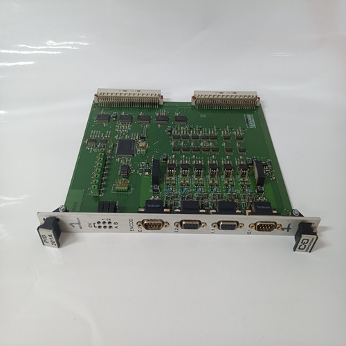
ALSTOM PIB1201A通道隔离卡件
辅助配电电子电源板SDCS-POW-1(参见单独章节)生成不同级别的电压。其中一些是通过CON-2电路板直接连接到电路板其他人被操纵,然后被转移。电子电源系统与以两种方式监控电压水平。有一个信号powerfail primary,用于监控输入POW-1板和a的电源电压
信号powerfail辅助,用于监控低电压电平。如果一个电压电平低于阈值产生跳闸信号。除此之外,还有一个用于5V电平。如果+5 V下降到跳闸电平以下,则通过硬件导致主重置。所有I/O寄存器
被强制为0,并且触发脉冲被抑制。RS485串行通信信道控制板有两个RS485通道。第一通道用于DCF 501/502的励磁机控制,DCF 503/504或DCF 601/602(端子X16:1…3)
第二个用于控制面板(CDP),位于端子X33或X34。端子X33和X34接线内部并联。
DDCS信道集成控制板SDCS-CON-2具有集成的DDCS(数字驱动控制系统)通道传输速率敢达4 Mbit/s。该信道(V260)例如:。可用于现场总线模块。终端X16:4和5用于模块。
SDCS-POW-1板专为DCS 500设计
转换器模块和安装在电子支架上。该板用于所有类型的与电流或电压无关的模块范围
SDCS-POW-1在回扫配置中基于切换模式工作。它为SDCS-CON-1和所有其他电子板。输入电压可以是通过开关SW1选择230 V AC或至115 V AC。下图显示了选择AC输入电压的说明并且用于选择编码器电源电压。
如果SDCS-CON-1带有SDCS-IOB-1板,或SDCS-CON-2(不带I/O板IOB-3)一起当脉冲编码器用于速度测量时,增量编码器电源电压必须通过跳线X5、X4和X3选择。这两个端子用于向现有端子添加额外电容,以增加电源缓冲时间。更多详细数据可通过ABB代表索取。电源接口板用于转换器模块型号C1。有两种不同版本
使用中。使用的类型有:-用于25 A、50 A和75 A转换器的SDCS-PIN-11500V时-600 V时50 A转换器的SDCS引脚12SDCS-PIN-1x板包括:-点火脉冲电路和脉冲变压器-通过电流测量电枢电流变压器
-晶闸管保护用缓冲电路(由RC电路和MOV元件组成)
Auxiliary power distribution
The electronic power supply board SDCS-POW-1
(see separate chapter) generates different levels of
voltages. Some of them are transferred via the
CON-2 board directly to the boards, where they are
used, others are manipulated and then transfered.The electronic power supply system with the different
voltage levels is monitored in two ways. There is a
signal powerfail primary, which monitors the input
power supply voltage of the POW-1 board and a
signal powerfail secondary, which monitors the low
voltage levels. If one voltage level drops below the
threshold a trip signal is generated.In addition to that there is a monitoring function for the
5 V level. If +5 V drops under the tripping level, it
causes a master reset by hardware. All I/O registers
are forced to 0 and the firing pulses are suppressed.RS485 serial communication channels
The control board has two RS485 channels. The first
channel is for field exciter control of DCF 501/502,
DCF 503/504 or DCF 601/602 (terminals X16:1...3)
and the second for the control panel (CDP) at terminals X33 or X34. The terminals X33 and X34 are wired
up in parallel internally.
DDCS Channel integrated
The control board SDCS-CON-2 has an integrated
DDCS (Digital Drive Control System) channel with a
tranfer rate up to 4 Mbits/s. This channel (V260) e.g.
can be used for fieldbus modules. The terminals
X16:4 and 5 are provided for power supply of the
modules.The SDCS-POW-1 board is designed for DCS 500
converter modules and is mounted on the electronic support. This board is used for all types of
modules independant from current or voltage
range.
The SDCS-POW-1 works on a switched mode basis in fly back configuration. It generates all necessary DC voltages for the SDCS-CON-1 and all
other electronic boards. The input voltage can be
selected via the switch SW1 either to 230 V AC or
to 115 V AC. The following figure shows the instructions for the selection of the AC input voltage
and for the selection of the encoder supply voltage.
If an SDCS-CON-1 with SDCS-IOB-1 board, or an
SDCS-CON-2 (without I/O board IOB-3) together
with a pulse encoder is used for speed measurement, the incremental encoder supply voltage must
be selected by jumpers X5, X4 and X3.These two terminals are used to add additional capacitance to the existing ones to increase the
mains buffering time. More detailed data is available on request via your ABB representative.The power interface board is used for converter
modules model C1. There are 2 different versions
in use. The used types are:
- SDCS-PIN-11 for 25 A, 50 A and 75 A converters
at 500V
- SDCS PIN-12 for 50 A converters at 600 V
The SDCS-PIN-1x boards consists of:
- firing pulse circuits and pulse transformers
- measurement of the armature current via current
transformers
- snubber circuit for thyristors protection
(consists of RC circuits and MOV elements)

