


")
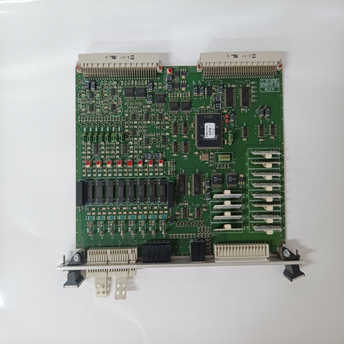
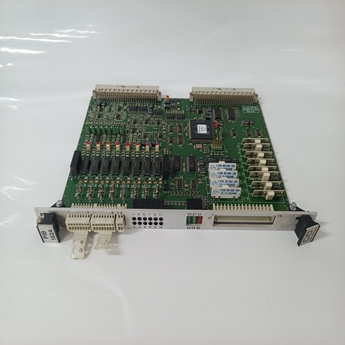
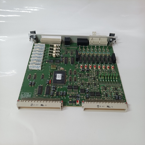
ALSTOM 3BEB0180卡件配套控制
存储器电路和备份包括系统和参数值的程序存储在闪存PROM D33和D34中。不同的程序可以直接下载到舞会。应用函数和参数值保存在闪存PROM D35中。
故障和报警信息以静态方式存储RAM电路。它们的备用电容器为1F、 持续至少8小时,通常为几小时天。充电大约需要30分钟备用电容器。
ASIC功能
ASIC=专用集成电路
大多数测量和控制功能用于:DCS500在ASIC中完成:
-与控制面板通信(RS 485)
-与励磁机通信(RS 485)
-测量
-看门狗功能
-A/D和D/A转换控制
晶闸管触发脉冲产生
看门狗功能
控制板有一个内部监视器。这个看门狗控制控制板的运行
程序如果看门狗跳闸,它具有以下功能影响:
-FPROM编程电压被强制为低。
-晶闸管点火控制被重置和禁用。
-数字输出被强制为低。
-可编程模拟输出重置为零,0V。RS485串行通信信道
控制板有两个RS485通道。这个第一个通道用于励磁机控制(端子X16:1…3)和第二个用于控制面板
(CDP 310)在端子X33或X34处。端子X33和X34内部并联连接。辅助配电
电子电源板POW-1(参见单独章节)生成不同级别的电压。其中一些是通过CON-1电路板直接连接到电路板
其他人被操纵,然后被转移。以两种方式监控具有不同电压电平的电子电源系统。那里是一个信号powerfail主电路,用于监控POW-1板的输入电源电压一个信号powerfail辅助,用于监控低电压电平。如果一个电压电平低于产生阈值a跳闸信号。除此之外,还具有以下监控功能:5V电平。如果+5V下降到跳闸电平以下,
它通过硬件导致主机复位。所有I/O寄存器被强制为0,触发脉冲被抑制。
Memory circuits and the back-up
The program including system and parameter values is stored at Flash PROMs D33 and D34. Different programs can be downloaded directly to these
PROMs. Application functionallity and parameter
values are saved in the Flash PROM D35.
Fault and Alarm messages are stored in static
RAM circuits. They have a back up capacitor of 1
F, which lasts minimum 8 hours, typically several
days. It takes about 30 minutes to charge the
backup capacitor.
ASIC function
ASIC = Application Specific Integrated Circuit
Most of the measurements and control functions for
the DCS500 are done in the ASIC:
- communication with control panel (RS 485)
- communication with field exciters (RS 485)
- measurement
- watchdog function
- A/D and D/A-conversion control
- thyristor firing pulse generation
Watchdog function
The control board has an internal watchdog. The
watchdog controls the running of the control board
program. If the watchdog trips, it has the following
effects:
- FPROM programming voltage is forced low.
- Thyristor firing control is reset and disabled.
- Digital outputs are forced low.
- Programmable analogue outputs are reset to
zero, 0V.RS485 serial communication channels
The control board has two RS485 channels. The
first channel is for field exciter control (terminals
X16:1...3) and the second for the control panel
(CDP 310) at terminals X33 or X34. The terminals
X33 and X34 are wired up in parallel internally.Auxiliary power distribution
The electronic power supply board POW-1 (see
separate chapter) generates different levels of
voltages. Some of them are transferred via the
CON-1 board directly to the boards, where they are
used, others are manipulated and then transfered.The electronic power supply system with the different voltage levels is monitored in two ways. There
is a signal powerfail primary, which monitors the input power supply voltage of the POW-1 board and
a signal powerfail secondary, which monitors the
low voltage levels. If one voltage level drops below
the threshold a trip signal is generated.
In addition to that there is a monitoring function for
the 5 V level. If +5 V drops under the tripping level,
it causes a master reset by hardware. All I/O registers are forced to 0 and the firing pulses are suppressed.

