


")
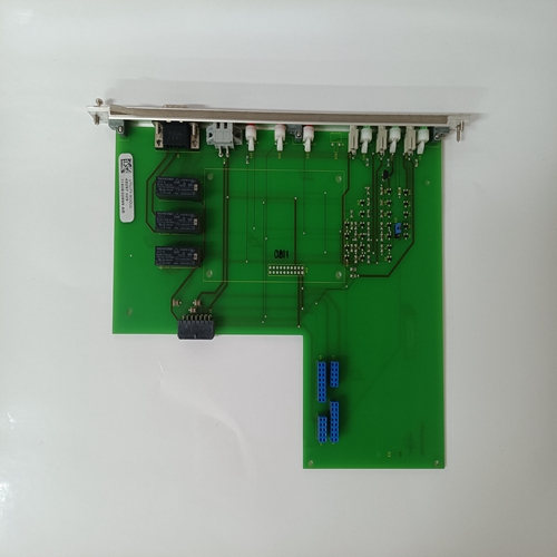
ALSTOM 43297029,控制器模块
项目规划/维护说明/附加信息
▶ 在调试放大器之前,必须确保设置了印刷电路板上的DIL开关根据相关应用。
▶ 在所提供的条件下,参数设置如下(参数设置参见第8至10页):最大斜坡时间=5秒,导频电流=100 mA,最大输出电流=800 mA,时钟频率=200 Hz。
▶ 放大器卡只能在断电时组装。
▶ 电磁阀连接不得使用带续流二极管或LED显示器的接头。
▶ 只能使用Ri>100 kΩ的仪器在板卡上进行测量。
▶ 测量零点(M0)与0 V工作电压相比增加+9 V,且未隔离,即-9 V调节电压≙ 0V工作电压。因此,不要将测量零点(M0)连接到0V工作电压。
▶ 对于开关指令值,必须使用带有镀金触点的继电器(低电压、低电流)。
▶ 始终屏蔽命令值线,在板卡一侧将屏蔽接地,另一侧打开。卡必须是通过端子6或8接地。如果不存在系统接地,则连接0 V工作电压。
▶ 建议:同时屏蔽电磁线圈导体。对于长度不超过50 m的螺线管导线,应使用LiYCY 1.5 mm2线型。如需更多长度,请联系我们。
▶ 与架空线路、无线电和雷达系统的距离必须至少为1米。
▶ 不要将电磁线圈导线和信号线放置在电源线附近。
▶ 板卡上平滑电容器的充电功率要求预熔丝具有缓慢熔断特性。
▶ 通知:
如果使用差分输入,则必须始终同时连接或断开两个输入。故障排除
如果放大器卡不工作,请执行以下步骤
故障排除需要:
1.工作电压是否可用?触点24(交流)对18(交流)的测量
2.卡上的保险丝有故障吗?
3.板卡上是否有内部±9 V工作电压?
4.如果使用内部命令值电位计,
10(交流)至12(交流)之间的电桥是否可用?
5.外部电位计是否正确连接?
6.差分输入是否正确连接?
控制:参考电位为30(交流)0至+10 V至28(交流)
7.电磁阀是否正确连接?
如果拔下板卡,电阻约为20Ω至30Ω 或5Ω至8Ω必须在触点22ac和20ac取决于阀类型。
括号中连接名称的修改仅适用于VT-VSPA1-1型。
通知:输出级在超温时关闭(例如,由于过载)。该错误由“H2”指示灯熄灭。
如果输入“4至20 mA”的电缆断开,“准备“操作”信号复位,“H2”LED将熄灭,
也以下适用于组件系列11:如果电磁线圈导体短路或电缆断裂,则“准备运行”输出将计时,并且“H2”LED将以0.5至2 Hz的频率快速闪烁因为指令值同时大于2%。
Project planning/maintenance instructions/additional information
▶ It has to be ensured before commissioning of the amplifi ers that the DIL switches on the printed circuit board are set
according to the relevant application.
▶ In the condition as supplied the parameters are set as follows (for the parameter setting refer to pages 8 to 10):
Max. ramp time = 5 s, pilot current = 100 mA, max. output current = 800 mA, clock frequency = 200 Hz.
▶ The amplifi er card may only be assembled when de-energized.
▶ No connectors with free-wheeling diodes or LED displays must be used for solenoid connection.
▶ Only carry out measurements at the card using instruments Ri > 100 kΩ.
▶ Measurement zero (M0) is increased by +9 V compared to 0 V operating voltage and not isolated, i.e. –9 V regulated
voltage ≙ 0 V operating voltage. Thus, do not connect measurement zero (M0) to 0 V operating voltage.
▶ For switching command values, relays with gold-plated contacts have to be used (low voltages, low currents).
▶ Always shield command value lines, connect shielding to earth on the card-side, other side open. The card has to be
connected to the earth via terminal 6 or 8. If no system earth exists, connect 0 V operating voltage.
▶ Recommendation:
Also shield the solenoid conductor. For solenoid conductors up to 50 m in length, use the line type LiYCY 1.5 mm2.
For greater lengths, please contact us.
▶ The distance to aerial lines, radios, and radar systems has to be 1 m at least.
▶ Do not lay solenoid conductors and signal lines near power lines.
▶ The charging power of the smoothing capacitor on the card requires the pre-fuses to be of a slow-blowing nature.
▶ Notice:
If the diff erential input is used, both inputs must always be connected or disconnected at the same time. Troubleshooting
If the amplifier cards do not function, the following steps
are required for troubleshooting:
1. Operating voltage available?
Measurement of contacts 24(ac) against 18(ac)
2. Fuse on the card faulty?
3. Internal ±9 V operating voltage available on the card?
4. If the internal command value potentiometers are used,
is the bridge from 10(ac) to 12(ac) available?
5. Is the external potentiometer correctly connected?
6. Is the differential input correctly connected?
Control: Reference potential to 30(ac)
0 to +10 V to 28(ac)
7. Is the solenoid correctly connected?
If the card is removed, a resistance of approx. 20 Ω
to 30 Ω or 5 Ω to 8 Ω has to be measurable between
contacts 22ac and 20ac depending on the valve type.
The amendment of the connection designations in brackets
only applies to type VT-VSPA1-1.
Notice:
The output stage switches off at overtemperature
(e.g. due to overload). This error is displayed by the
"H2" LED going out.
In case of cable break of input "4 to 20 mA", the "ready for
operation" signal is reset and the "H2" LED will go out,
as well.
The following applies from component series 11:
In case of short-circuit or cable break of the solenoid conductor, the ready for operation output will clock and the
"H2" LED will flash with a frequency of 0.5 to 2 Hz as soon
as the command value is simultaneously > 2 %.

