


")
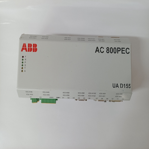
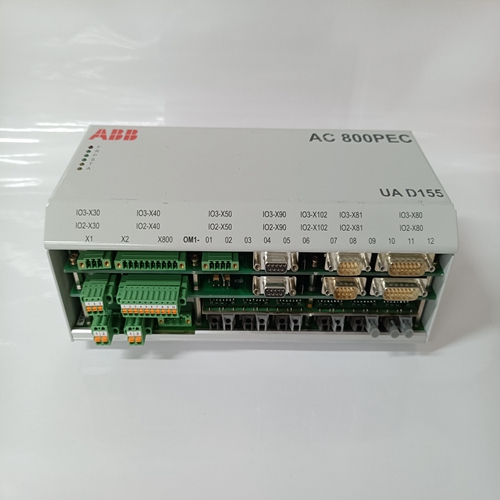
UAD155A0111,DCS控制模块
电阻器R54和R56、电位计R55和电容器C12决定欠频限制操作阈值。齐纳二极管Z3和
电容器C9和C10保护集成电路免受损坏如果出现过大的电压尖峰。安装:电压调节器可安装在任何位置,无需影响其操作特性。电压调节器为对流式冷却。保留suf 调节器周围有足够的散热空间并且用于进行电连接和控制调节。攀登任何位置的电压调节器,无冲击和振动过量,且环境温度不超过其环境温度操作限制。
互连:将调节器连接到发电机系统
本节中的说明和连接图中所示与发电机组一起提供。整体轮廓见图3
显示调节器安装装置位置的图纸以及电压调节器的部分。参见图4至图11了解典型的电压的互连图和电气示意图监管者使用14号或更大的导线连接电压
监管者单相100至600伏交流感应(端子El和E3):
设计用于单相感应的标准KCR 760电压调节器具有如图4所示的内部感应变压器(T1)
变压器在一次绕组上设有分接头
用于感应电压为100至139、200至228、216至265、375至458、432至528,以及540至600VAC。变压器一次绕组抽头相同 预计起飞时间对应的标称电压为120、208、240、416,480和600伏交流电压。为了获得正确的操作,内部导线:电压调节器端子E3必须连接到正确的一次电源上分接变压器T1。调节器内的电线连接至感应变压器次级绕组如图4所示。
三相100至600 Vac感应(端子El、E2和E3):当调节器设计用于三相感应,包括两个感应变压器(T1和T3),如图5所示。
除非另有规定 采购订单中的ed,监管机构
传感变压器均包括多抽头一次绕组,用于:与单相100至600中所述的感应电压一起使用真空感应程序。
要正常工作,请连接电压调节器的内部导线端子E3连接到变压器T1上的正确初级绕组抽头,并将内部导线从电压调节器端子E2连接到变压器T3上相应的初级绕组抽头。连接调节器内至传感变压器的电线二次绕组如图5所示。
Mounting: The voltage regulator can be mounted in any position without affecting its operating characteristics. The voltage regulator is convection cooled. Retain suf cient space around the regulator for heat dissipation and for making electrical connections and controls adjustments. Mount the voltage regulator in any location where shock and vibration are not excessive and the ambient temperature does not exceed its ambient operational limits. Interconnection: Connect the regulator to the generator system as instructed in this section and as shown in the connection diagram provided with the generator set. See Figure 3 for an overall outline drawing that shows the location of regulator mounting provision and parts of the voltage regulator. See Figures 4 to 11 for a typical interconnection diagrams and electrical schematics of the voltage regulator. Use 14 gauge or larger wire for connections to the voltage regulator. Single-phase 100 to 600 Vac sensing (terminals El and E3): The standard KCR 760 voltage regulator designed for single phase sensing has an internal sensing transformer (T1) as shown in Figure 4. This transformer is provided with taps on the primary winding for sensing voltages of 100 to 139, 200 to 228, 216 to 265, 375 to 458, 432 to 528, and 540 to 600 Vac. The transformer primary winding taps are identi ed with the corresponding nominal voltages, which are 120, 208, 240, 416, 480, and 600. Vac. To obtain proper operation the internal wire from voltage regulator terminal E3 must be connected onto the correct primary tap on transformer T1. Electrical wires within the regulator connect to the sensing transformer secondary winding as shown in Figure 4. Three-phase 100 to 600 Vac sensing (terminals El, E2, and E3): When the regulator is designed for three-phase sensing, it includes two sensing transformers (T1 and T3) as shown in Figure 5. Except when otherwise speci ed in the purchase order, the regulator sensing transformers will both include multi-tap primary winding for use with the sensing voltages described in the single phase 100 to 600 Vac sensing procedure. To properly operate, connect the internal wire from voltage regulator terminal E3 to the correct primary winding tap on transformer T1, and connect the internal wire from voltage regulator terminal E2 to the corresponding primary winding tap on transformer T3. Connect electrical wires within the regulator to the sensing transformers secondary winding as shown in Figure 5.

