


")
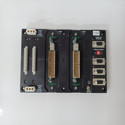
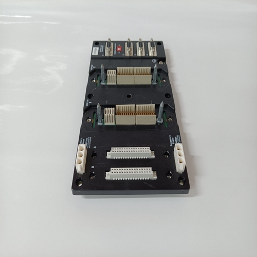
FCP280底板
感测变压器次级中产生的电压
T2次级中产生的电压矢量相加。这动作向传感二极管提供电压,即降压传感电压和并联电流互感器
通过T2的信号。感测电路 er直流输出为 过滤和应用至误差检测器和欠频极限。
当电阻(单位功率因数)负载连接到发电机时,下降电位计两端出现的电压导致感应
电压90度,两个电压的矢量和接近与原始感测电压相同;因此,几乎没有变化发生在发电机输出电压中。
当滞后功率因数(感应)负载连接到发电机,下降电位计两端的电压变得更高与感测电压同相,以及两者的组合矢量电压导致更大的电压被施加到感测
由于调节器的作用是在感觉直肌 ers
调节器通过降低发电机输出作出反应
电压当领先功率因数(电容性)负载连接到发电机,下降电位计两端的电压变为与感测电压的相位以及两者的组合矢量电压导致施加到感测recti的电压较小 呃。
然后调节器通过增加发电机电压作出反应。两台或多台发电机并联运行期间,相互连接
对于无功电压降,如果 其中一台发电机的eld励磁变得过大并导致循环电流 哦,在发电机,循环电流将作为感应负载出现在发电机励磁过大,另一个具有电容性负载
发电机。并联部件R4和T2将导致电压发电机调节器过大 eld激励,以降低
发电机电压,而其他发电机的电压调节器将增加发电机电压。
并联交叉电流补偿模式下并联发电机运行期间的传感电路:并联交叉电流赔偿允许两台或多台并联发电机共享感应无功负载
在以下情况下,发电机系统输出电压不会下降或降低:线路电流成比例且同相。这是通过以下方式实现的:
上述并联无功电压的动作和电路下垂补偿和电流互感器的互连
闭合串联回路中的二次回路。循环电流导致系统
如前所述,对并联电压降补偿作出反应
The voltage developed in the secondary of the sensing transformer(s)
and the voltage developed in the secondary of T2 add vectorially. This
action provides a voltage to the sensing diodes that is the vector sum of
the stepped down sensing voltage and the parallel current transformer
signal through T2. The sensing recti er dc output is ltered and applied
to the error detector and underfrequency limit.
When a resistive (unity power factor) load is connected to the generator,
the voltage that appears across the droop potentiometer leads the sensing
voltage by 90 degrees, and the vector sum of the two voltages is nearly
the same as the original sensing voltage; consequently, almost no change
occurs in generator output voltage.
When lagging power factor (inductive) load is connected to the
generator, the voltage across the droop potentiometer becomes more
in phase with the sensing voltage, and the combined vectors of the two
voltages result in a larger voltage being applied to the sensing recti ers.
Since the action of the regulator is to maintain a constant voltage at the
sensing recti ers, the regulator reacts by decreasing the generator output
voltage.
When a leading power factor (capacitive) load is connected to the
generator, the voltage across the droop potentiometer becomes out of
phase with the sensing voltage, and the combined vectors of the two
voltages result in a smaller voltage being applied to the sensing recti ers.
Then the regulator reacts by increasing the generator voltage.During parallel operation of two or more generators interconnected
for reactive voltage droop, if eld excitation on one of the generators
becomes excessive and causes a circulating current to ow between the
generators, the circulating current will appear as an inductive load to the
generator with excessive excitation and a capacitive load to the other
generator(s). The parallel components R4 and T2 will cause the voltage
regulator of the generator with excessive eld excitation to decrease the
generator voltage while the voltage regulators of the other generator(s)
will increase the generator voltage.
Sensing circuit during parallel generator operation in parallel crosscurrent compensation mode: Parallel cross-current compensation
allows two or more paralleled generators to share inductive reactive loads
with no droop or decrease in the generator system output voltage when
the line currents are proportional and in phase. This is accomplished by
the action and circuitry described previously for parallel reactive voltage
droop compensation and the interconnection of the current transformer
secondaries in a closed series loop. Circulating currents cause the system
to react as described previously for parallel voltage droop compensation

