


")
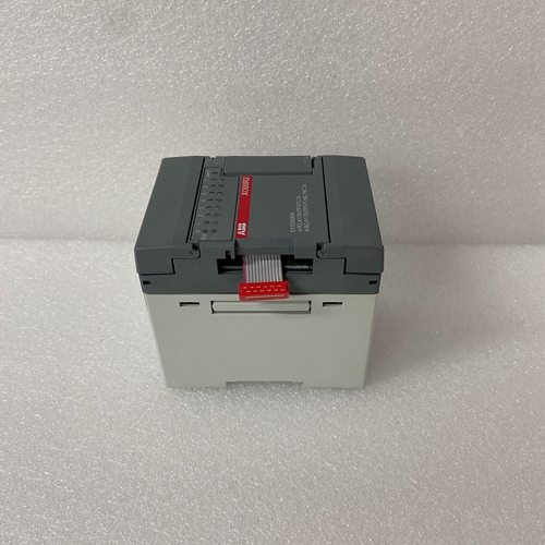
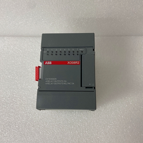
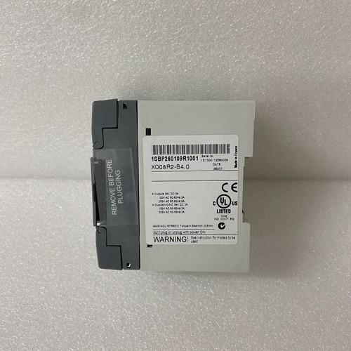
XO08R2数控模块
旋转变压器系统
输出信号通过R/D硬件电路开发,以实现最小相位滞后,并具有:由电机速度和R/D限制确定的最大频率。它提供了一个可配置的(ENCOUT)电机每旋转一圈,分辨率高达16384行(65536个四路计数)
轴索引脉冲(INDEXPOS)的位置可在以下分解器系统上变化:360度电角度的反馈信号。对于单速分解器,这意味着您可以改变该信号在一个机械旋转中的位置。对于多速旋转变压器机械位置变化由分解器的极对计数确定(例如,三速分解器在1/3转内给出脉冲的机械变化)。
编码器系统
输出信号是实际编码器反馈信号,在驱动器的电机参数。它可以按2的倍数缩小(编码:1、2、4、8、16)并且具有3MHz的最大频率限制。用于指示异常操作状态:
如果位置保持功能激活,OPMODE编号将以1 Hz的频率闪烁速度
如果检测到故障,将显示闪烁代码以识别故障。
某些代码由两个或更多数字组成(请参阅故障排除部分)。通常,这些故障将导致锁存禁用(有时可通过软件开关控制)。
要清除故障,请切换远程启用(过电流除外)
如果编码器初始化功能(ENCSTART)激活,则OPMODE数字将以3 Hz的频率闪烁。SERVOSTAR CD-Lite能够采用不同的操作模式。这是一家工厂配置为OPMODE=1(模拟速度控制器),但可由用户重新配置。并非全部命令和变量在每个操作模式下都是活动的或有意义的。OPMODE=1模拟速度控制器。SERVOSTAR CD Lite配置为速度回路控制器,通过±10V模拟输入信号进行控制。
指令速度与输入电压成比例。OPMODE=3模拟转矩(电流)控制器。SERVOSTAR CD-Lite是
配置为扭矩回路控制器,并通过±10 V模拟控制
输入信号。指令电流与输入电压成比例。
系统输入/输出
本节讨论C3连接器的输入/输出功能(C2上的恒温器输入除外,请参阅附录)。电气规格见《快速启动指南》。模拟输入(ANIN1)
速度或扭矩回路可从模拟电压源接收其指令,并可选择通过OPMODE变量。SERVOSTAR CD-Lite的模拟输入是差分的。这意味着两个输入端接收到的信号彼此相减以产生“差”
用于命令系统的其余部分。这种类型的输入具有高度的抗噪性并且,在许多情况下,将允许系统之间的接地隔离。该模拟输入也具有低电平通过滤波器(ANLPFHZ)防止高频噪声进入系统。
Resolver Systems
The output signal is developed through the R/D hardware circuitry for minimal phase lag and has
a maximum frequency determined by the motor speed and R/D limits. It provides a configurable
(ENCOUT) resolution of up to 16384 lines (65536 quad counts) per revolution of the motor
shaft. The placement of the index pulse (INDEXPOS) can be varied on resolver systems within
360 electrical degrees of the feedback signal. For single-speed resolvers, this means you can vary
the position of this signal over one mechanical revolution. For multi-speed resolvers, the
mechanical position variation is determined by the pole-pair count of the resolver (e.g. threespeed resolver gives mechanical variation of the pulse within 1/3 of a revolution).
Encoder Systems
The output signal is the actual encoder feedback signal that is pre-configured (MENCRES) in the
drive’s motor parameters. It can be scaled down by multiples of two (ENCOUTO: 1, 2, 4, 8, 16)
and has a maximum frequency limit of 3 MHz. Used to indicate an abnormal operating state:
If the position hold feature is active, the OPMODE number will flash at a 1 Hz
rate.
If a fault was detected, a flashing code will be displayed to identify the fault.
Some codes consist of a sequence of two or more digits (see Troubleshooting
section). In general, these faults will cause a latched disable (sometimes
controllable through software switches). To clear fault, toggle remote enable
(except for OverCurrent).
If the encoder initialization function (ENCSTART) is active, the OPMODE
number will flash at a 3 Hz rate. The SERVOSTAR CD-Lite has the ability to assume different modes of operation. It is factory
configured in OPMODE=1 (Analog Velocity Controller) but may be reconfigured by the user. Not all
commands and variables are active or meaningful in every OPMODE.
OPMODE = 1 Analog Velocity Controller. The SERVOSTAR CD-Lite is configured as a
velocity-loop controller and is controlled via a ± 10V analog input signal.
The commanded velocity is proportional to the input voltage.
OPMODE = 3 Analog Torque (Current) Controller. The SERVOSTAR CD-Lite is
configured as a torque-loop controller and is controlled via a ± 10 V analog
input signal. The commanded current is proportional to the input voltage.
System I/O
This section discussions the I/O features of the C3 connector (except for the Thermostat input on C2 see
appendix). Electrical specifications are in the Quick Start Guide.
Analog Input (ANIN1)
The velocity or torque loop can receive its command from an analog voltage source and is selectable
through the OPMODE variable. The analog input to the SERVOSTAR CD-Lite is differential. This
means that the signals received at the two inputs are subtracted from each other to create a ‘difference,’
that is used to command the rest of the system. This type of input has a high degree of noise immunity
and, in many cases, will allow for ground isolation between systems. This analog input also has a low
pass filter (ANLPFHZ) to prevent high frequency noise from entering the system.

