


")
IS215UCVEM08B燃机模块
模拟输入模块提供多达32个低电压或电流模拟输入信号。全部的模块的通道输入彼此电阻隔离,并电流隔离来自系统环境。基本模块可以配置为满足一系列输入规格,不同的配置可从模块类型编号中识别(见第1.3节,规范)。电路三重化和表决程序使模块具有单容错性。前面板信道选择器和测试点可对任何信道进行计量,指示器显示电路在线状态和模块的健康状况。
与“热修复”兼容的模块可安装在SC300E机箱通过物理编码防止“错误开槽”。SC300E系统软件通过内置硬件标识符识别模块。通道输入通过机箱上的DIN 41612“后插拔”系统连接至模块背板。本文件旨在提供对模拟输入模块,足以使基本维护操作在场物理模拟输入模块是一个9U高PCB,带有集成前面板和后连接器;
一插件子板承载公共接口电路。
总平面图、位置连接器、前面板组件和321/320配置链路如图1-1所示。机械编码块所有输入/输出模块都带有两个机械编码块,配备有匹配的引脚机箱中的相应块中有孔,防止模块插入错误的插槽。模块块中的引脚在工厂按照以下方式安装:将模块和相应的固定螺钉从机箱编码块上拆下,以便:启用安装。未使用的孔用固定螺钉堵塞。底盘机械编码该模块的模块配置如图2-1所示。现场电路图2-2所示的现场输入回路是安全所需的绝对最小值模拟输入的连接。但是,我们建议使用他们的16信道模拟输入终端卡TAI16***,可提供现场电源、远程和本地报警指示、瞬态抑制、信号和保护接地设施。
图2-3显示了电流输入模块的终端卡。操作模式321或320模式设置了阈值,该阈值决定了电路的容量
降级,同时仍保持整体操作。设置320模式意味着系统
将在三个可维修电路中的两个电路上继续工作;如果这个数字下降到1:1在三个数据中,最后读取的数据被保持。在321模式下,系统将继续运行:三分之一的可维修电路;如果失败,则保持最后读取的数据,并且模块离线。
PURPOSE
The Analogue Input Module provides up to 32, low voltage or current analogue input signals. All
channel inputs into the module are resistively isolated from each other and galvanically isolated
from the system environment.
The basic module can be configured to meet a range of input specifications, the different
configurations can be identified from the module type number (see Section 1.3, Specification).
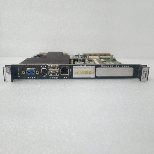
Circuit triplication and voting procedures make the module single-fault tolerant. A front panel
Channel selector and test points enable the metering of any channel, and indicators show the
circuit on-line status and the health of the module.
The module, which is compatible with ‘hot repair’, can be fitted in any of the ten I/O slots in the
SC300E Chassis, ‘wrong slotting’ is prevented by physical coding. The SC300E system
software identifies the module via a built-in hardware identifier.
Channel inputs are wired to the module via the DIN 41612 ‘rear plug-up’ system on the chassis
backplane. This document is intended to provide a general understanding of the function of the
Analogue Input Module, sufficient to enable basic maintenance operations to be effected in the
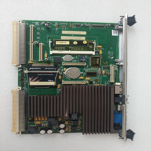
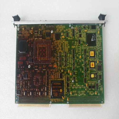
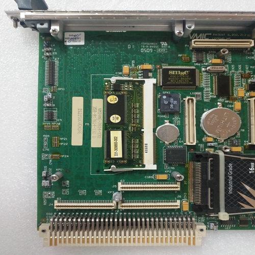
field.PHYSICAL
The Analogue Input Module is a 9U high PCB with integral front panel and rear connectors; a
plug-in daughter board carries the Common Interface circuits.The general layout, location of the
connectors, front panel components and the 321/320 configuration link is shown in Figure 1-1.
Mechanical coding blocks
All Input/Output modules carry two mechanical coding blocks equipped with pins which mate
with holes in corresponding blocks in the chassis and prevent the module being inserted into
the wrong slot. The pins in the module blocks are factory installed in a pattern determined by
the module and corresponding set screws are removed from the chassis coding blocks to
enable fitting. Unused holes are plugged with set screws. The chassis mechanical coding
block configuration for this module is shown in Figure 2-1.Field circuits
The field input loop shown in Figure 2-2 is the absolute minimum required for the safe
connection of analogue inputs. We however, recommend the use of their 16 Channel
Analogue Input termination cards TAI16*** which can offer field power supplies, remote and
local alarm indication, transient suppression and signal and protective ground facilities.
Figure 2-3 shows a termination card for a current input module.Modes of operation
The 321 or 320 mode sets the threshold that determines how much of the circuit can be
degraded while still preserving overall operation. Setting the 320 mode means that the system
will continue to function with two out of three serviceable circuits; if the number falls to one out
of three the last read data is maintained. In 321 mode the system will continue to function with
one out of three serviceable circuits; if that fails the last read data is maintained and the
module is taken off-line.

