


")
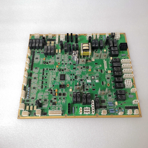
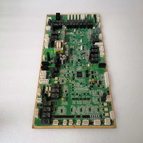
IS200WETBH1ABA通用电气卡件
保护警报。六个保护报警指示器提供DECS-100保护功能的状态。
报警指示器包括过励磁停机、过励磁限制、欠励磁限制,发电机过电压、发电机感应损失和欠频。当使用DECS-100保护时功能检测报警条件,相应的指示灯从黑色变为红色。控制状态。两个控制状态指示器指示VAR/PF和手动模式何时激活。
当FCR控制模式激活时,手动模式激活指示灯从黑色变为红色。这个DECS-100在AVR模式下运行时,VAR/PF模式激活指示灯从黑色变为红色并且选择功率因数或VAR的校正。
开关状态。三个开关状态指示灯指示DECS-100控制输入何时打开或关闭当用户提供的触点位于时,52JK开关打开指示灯从黑色变为红色端子52J和52K闭合。当该控制输入打开时,可以选择PF或VAR模式在计量、操作和报警屏幕的操作选项卡上进行。52LM开关闭合当终端52L和52M处的用户提供触点处于以下状态时,指示器从黑色变为红色:关闭当该控制输入关闭时,并联控制和下垂处于非活动状态。当用户提供的端子VM和VMC触点处于以下状态时,VM开关闭合指示灯从黑色变为红色:关闭当该控制输入关闭时,电压匹配功能激活。
计量信号
计量信号指示灯闪烁,以指示何时启动计量。数指示器旁边跟踪计量和状态指示器更新的次数。什么时候单击“计量”按钮或单击菜单栏上的“计量”,然后单击“禁用计量”计量信号指示灯停止闪烁,计量更新计数器停止递增,并且计量功能停止更新。BESTCOMS可通过自动计算PID参数来设置发电机稳定性。PID代表比例、积分、微分。“比例”一词的意思是DECS-100输出与观察到的变化量成比例或相对。积分意味着DECS-100输出与观察到变化的时间量成比例。积分作用这消除了偏移。导数意味着DECS-100输出与所需速率成比例激发变化。微分动作避免了励磁过冲。
BESTCOMS在用户选择发电机频率后自动计算PID值,发电机时间常数(T’do)和励磁机时间常数(Texc)。使用BESTCOMS,用户可以生成新的PID编号,添加到PID列表文件,并更新控制增益或中的AVR增益设置步骤响应屏幕。
点击PID按钮可访问PID窗口(图5-18)。只能单击PID按钮当控制增益屏幕的稳定范围设置被设置为值21时(设置为21允许通过PID窗口输入自定义稳定性设置。)然后,当控件的字段
更改或选择增益屏幕时,PID按钮从灰色变为黄色,按钮可以单击以查看PID窗口。修改、计算和更新PID编号后单击更新设置屏幕按钮关闭窗口。然后显示修改后的PID值在控制增益屏幕上。
Protection Alarms. Six protection alarm indicators provide the status of DECS-100 protection functions.
Alarm indicators include Overexcitation Shutdown, Overexcitation Limiting, Underexcitation Limiting,
Generator Overvoltage, Loss of Generator Sensing, and Underfrequency. When a DECS-100 protection
function detects an alarm condition, the appropriate indicator changes from black to red.
Control Status. Two Control Status indicators indicate when the VAR/PF and Manual modes are active.
The Manual Mode Active indicator changes from black to red when the FCR control mode is active. The
VAR/PF Mode Active indicator changes from black to red when the DECS-100 is operating in AVR mode
and correction of power factor or vars is selected.
Switch Status. Three Switch Status indicators indicate when the DECS-100 control inputs are open or
closed. The 52JK switch open indicator changes from black to red when the user-supplied contacts at
terminals 52J and 52K are closed. When this control input is open, selection of PF or VAR mode can be
made on the Operation tab of the Metering, Operation, and Alarms screen. The 52LM switch closed
indicator changes from black to red when the user-supplied contacts at terminals 52L and 52M are
closed. When this control input is closed, parallel control and droop is inactive. The VM switch closed indicator changes from black to red when the user-supplied contacts at terminals VM and VMC are
closed. When this control input is closed, the Voltage Matching function is active.
Metering Signal. The Metering Signal indicator flashes to indicate when metering is active. A number
beside the indicator tracks how many times the metering and status indicators have been updated. When
the Metering button is clicked or Metering on the Menu bar is clicked followed by Disable Metering, the
Metering Signal indicator stops flashing, the metering update counter stops incrementing, and the
metering functions stop being updated. BESTCOMS enables generator stability to be set through the automatic calculation of PID parameters.
PID stands for Proportional, Integral, Derivative. The word proportional means that the response of the
DECS-100 output is proportional or relative to the amount of change that is observed. Integral means that
the DECS-100 output is proportional to the amount of time that a change is observed. Integral action
eliminates offset. Derivative means that the DECS-100 output is proportional to the required rate of
excitation change. Derivative action avoids excitation overshoot.
BESTCOMS automatically calculates PID values after the user selects the generator frequency,
generator time constant (T'do), and exciter time constant (Texc). With BESTCOMS, the user may
generate new PID numbers, add to a PID list file, and update the AVR gain settings in the Control Gain or
Step Response screens.
The PID window (Figure 5-18) is accessed by clicking the PID button. The PID button can be clicked only
when the Stability Range setting of the Control Gain screen is set at a value of 21. (A setting of 21
enables the entry of custom stability settings through the PID window.) Then, when a field of the Control
Gain screen is changed or selected, the PID button changes from gray to yellow and the button can be
clicked to view the PID window. After the PID numbers are modified, calculated, and updated, the PID
window is closed by clicking the Update Setting Screen button. The modified PID values are then shown
on the Control Gain screen.

