


")
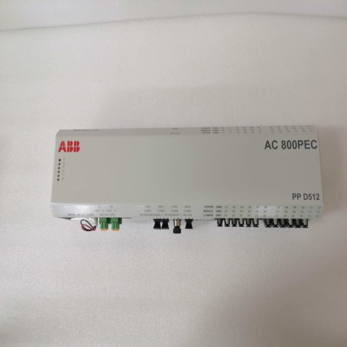
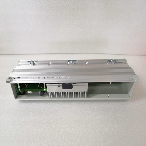
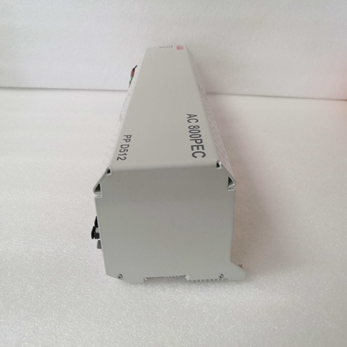
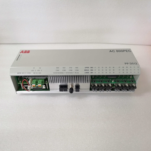
PPD512控制器
通信端口后面板上的RS-232端口使用DB-9母连接器。图4-4说明了引脚通信端口的分配,以及表4-4确定了RS-232连接器引脚
功能。标准通信电缆使用DB-9公连接器端接
对于与DECS-100的PC接口,如所示
图4-5典型应用的DECS-100连接
图4-6至图4-10说明了使用DECS-100的典型应用DECS-100操作功率来自永磁发电机(PMG)的应用,以及DECS-100采用三相电压传感。图4-7显示了另一种PMG应用,但具有单相电压感测。图4-8显示了DECS-100操作功率为从发电机输出(并联应用)导出,三相电压感应应用于DECS-100。图4-9显示了另一种分流应用,但具有单相传感。图4-10显示DECS-100由三相传感应用中的单相电站电源供电。
图4-11显示了在交叉电流中运行的两台并联发电机的典型连接图补偿(无功差动)模式。所示电阻器的值为0.1欧姆。这是典型的可用于设置负担的值。(确保电阻器的额定功率足以满足安装。)以下段落描述了CE(欧洲)的安装和布线要求社区)兼容安装。
安装DECS-100必须安装在接地的金属外壳(导管箱)内。检修面板应覆盖前面板显示器的开口。
装电线与下列端子连接的接线必须屏蔽。每个屏蔽应终止于:在导管箱外部接地。
•电流感应端子CT1和CT2
•继电器输出端子AL1和AL2
•无功/功率因数控制触点输入端子52J和52K
•并联发电机补偿端子52L和52M
•升高和降低触点输入端子6U、6D和7
•附件输入电压端子A和B
•电压匹配触点输入端子VM和VMC
1。标记并断开DECS-100的所有接线。确保绝缘接线端子,以防止短路。
2.启动原动机并执行所有发动机调速器调整。
3.完成所有初始调速器调整后,关闭原动机。
Communication Port
The RS-232 port on the rear panel uses a DB-9
female connector. Figure 4-4 Illustrates the pin
assignments of the communication port and
Table 4-4 Identifies the RS-232 connector pin
functions. A standard communication cable
terminated with a DB-9 male connector is used
for PC interface with the DECS-100 as shown in
Figure 4-5. DECS-100 Connections for Typical Applications
Figures 4-6 through 4-10 illustrate typical applications using the DECS-100. Figure 4-6 shows an
application where DECS-100 operating power is derived from a permanent magnet generator (PMG) and
three-phase voltage sensing is applied to the DECS-100. Figure 4-7 shows another PMG application but
with single-phase voltage sensing. Figure 4-8 shows an application where DECS-100 operating power is
derived from the generator output (shunt application) and three-phase voltage sensing is applied to the
DECS-100. Figure 4-9 shows another shunt application but with single-phase sensing. Figure 4-10 shows
a DECS-100 powered by single-phase station power in a three-phase sensing application.
Figure 4-11 shows a typical connection diagram for two paralleled generators operating in cross-current
compensation (reactive differential) mode. The resistors shown have a value of 0.1 ohms. This is a typical
value that can be used to set the burden. (Ensure that the resistor power rating is adequate for the
installation.) The following paragraphs describe the mounting and wiring requirements for a CE (European
Community) compliant installation.
Mounting
The DECS-100 must be mounted inside a grounded, metal enclosure (conduit box). An access panel
should cover the opening for the front panel display.
Wiring
Wiring connected to the terminals listed below must be shielded. Each shield should be terminated to
ground on the outside of the conduit box.
• Current sensing terminals CT1 and CT2
• Relay output terminals AL1 and AL2
• Var/Power Factor control contact input terminals 52J and 52K
• Parallel generator compensation terminals 52L and 52M
• Raise and lower contact input terminals 6U, 6D, and 7
• Accessory input voltage terminals A and B
• Voltage matching contact input terminals VM and VMC 1. Tag and disconnect all wiring to the DECS-100. Be sure to insulate the wire terminals to prevent a
short circuit.
2. Start the prime mover and perform all engine governor adjustments.
3. After all initial governor adjustments have been made, shut down the prime mover.

